Oscillation type electromagnetic power generator and method for manufacturing oscillation type electromagnetic power generator

a technology of oscillation type and electromagnetic power generator, which is applied in the direction of manufacturing dynamo-electric machines, dynamo-electric machines, electrical apparatus, etc., can solve the problems of lowering the combined output voltage, reducing and not knowing the dimensions of the reference magnet, so as to improve the efficiency of power generation and reduce the dimensions of the power generator. , the effect of effective obtaining the peak generated power

Active Publication Date: 2010-04-08
SUMIDA CORP
View PDF4 Cites 21 Cited by
  • Summary
  • Abstract
  • Description
  • Claims
  • Application Information

AI Technical Summary

Benefits of technology

[0015]According to the present invention, since the spacer for magnet, the magnet, the coil, and the coil gap can be optimally designed, an oscillation type electromagnetic power generator with enhanced power generation efficiency can be obtained.
[0016]According to the present invention, the optimal design of an oscillation type electrom

Problems solved by technology

If the requirement is not met, voltages generated with the plurality of coils are out of phase with one another and the respective voltages then cancel one another, thereby causing a problem of lowering a combined output voltage.
However, in Patent Document 1, there is no description about the necessity of matching a magnet pitch with a coil pitch and also no disclosure of how to define a reference magnet length.
Furthermore, there is no disclosure of how to concr

Method used


Image

  • Oscillation type electromagnetic power generator and method for manufacturing oscillation type electromagnetic power generator
  • Oscillation type electromagnetic power generator and method for manufacturing oscillation type electromagnetic power generator
  • Oscillation type electromagnetic power generator and method for manufacturing oscillation type electromagnetic power generator

Examples


Embodiment Construction

[0029]Hereinafter, an embodiment of the present invention will be described with reference to FIG. 1 to FIG. 12. In the present embodiment, an example in which the present invention is applied to an oscillation type electromagnetic power generator that generates electric power as a result of moving a magnet arranged in a solenoid coil by oscillation from the outside.

[0030]First, before describing a concrete example of the structure of an oscillation type electromagnetic power generator according to the present invention, a power generator including a movable magnet and a solenoid coil will be described with reference to FIG. 1 to FIG. 3.

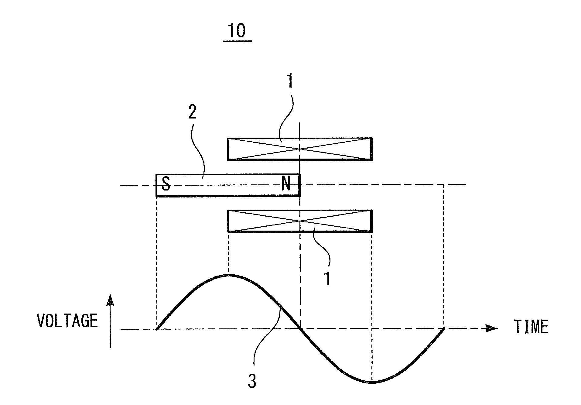
[0031]FIG. 1 illustrates an example of the structure of an oscillation type electromagnetic power generator 10 including one cylindrical magnet 2 and one solenoid coil 1, and also illustrates an example of an output voltage waveform.

[0032]The length of the solenoid coil 1 of the oscillation type electromagnetic power generator10 is substantially equa...


PUM

PropertyMeasurementUnit
Fractionaaaaaaaaaa
Fractionaaaaaaaaaa
Lengthaaaaaaaaaa

Abstract

A specific condition for enhancing the power generation efficiency of an oscillation type electromagnetic power generator is disclosed. Solenoid coils constituting the oscillation type electromagnetic power generator are wound in directions opposite to each other with a predetermined coil gap therebetween. Adjacent magnets of a movable magnet are connected to each other via a spacer having a predetermined thickness in such a manner that poles with the same polarity are opposed to each other. A coil pitch which is the total dimension of the coil length of one solenoid coil and the coil gap and a magnet pitch which is the total dimension of the magnet length of one magnet of the movable magnet and the thickness of the spacer are almost equal to each other, and the coil length is shorter than the magnet length.

Description

TECHNICAL FIELD[0001]The present invention relates to an oscillation type electromagnetic power generator that generates a power generation voltage, for example, by oscillating or moving a plurality of cylindrical magnets magnetized in the longitudinal direction thereof through a plurality of solenoid coils and to a method for manufacturing the oscillation type electromagnetic power generator. In particular, the present invention relates to an oscillation type electromagnetic power generator in which the generation efficiency thereof is enhanced by unifying a plurality of magnets in such a manner that the poles with the same polarity are opposed to each other at specified intervals and to a method for manufacturing such an oscillation type electromagnetic power generator.BACKGROUND ART[0002]In recent years, portable electronic apparatuses, such as portable telephone terminals and game machines, have been popularized, and the number of rechargeable batteries built in these apparatuse...

Claims


Application Information

Patent Timeline
IPC IPC(8): H02K35/02H02K15/00
CPCY10T29/49009H02K35/02
Inventor YOSHIDA, TETSUOAIZAWA, YUKIOSUGANUMA, SHIGEMIMASUDA, KENTARO
Owner SUMIDA CORP
Why Eureka
Try Eureka