Cold cathode tube lamp

a technology of cold cathode tubes and cathode tubes, which is applied in the direction of transit tubes, cathode-ray/electron beam tube circuit elements, structural circuit elements, etc., can solve the problems of increasing the size of backlights, difficult to light all cold cathode tubes, and difficulty in directly measuring capacitance, so as to prevent brightness variations

Inactive Publication Date: 2010-04-08
SHARP KK
View PDF8 Cites 6 Cited by
  • Summary
  • Abstract
  • Description
  • Claims
  • Application Information

AI Technical Summary

Benefits of technology

[0009]The present invention is devised to solve the above problems. An object of the invention is to provide a cold cathode tube lamp that has a ballast capacitor fitted to a discharge tube and yet can prevent variations in brightness.

Problems solved by technology

Thus, when an attempt is made to drive a plurality of cold cathode tube lamps connected in parallel, there arises the following inconvenience.
This makes it difficult to light all of the cold cathode tube lamps.
This, however, leads to inconveniences such as increased sizes of backlights.
Since the ballast capacitor connected to the discharge tube is housed inside the insulating rubber bush, it is difficult to measure the amount of capacitance directly by connecting a measuring device to the ballast capacitor.
That is, in the cold cathode tube lamp according to JP-A-10-177170 Publication, it is difficult to accurately grasp variations in the capacitance value of the ballast capacitor.
As a result, due to the variations in the capacitance value of the ballast capacitor, the brightness of the cold cathode tube lamp varies disadvantageously.

Method used


Image

  • Cold cathode tube lamp
  • Cold cathode tube lamp
  • Cold cathode tube lamp

Examples


first preferred embodiment

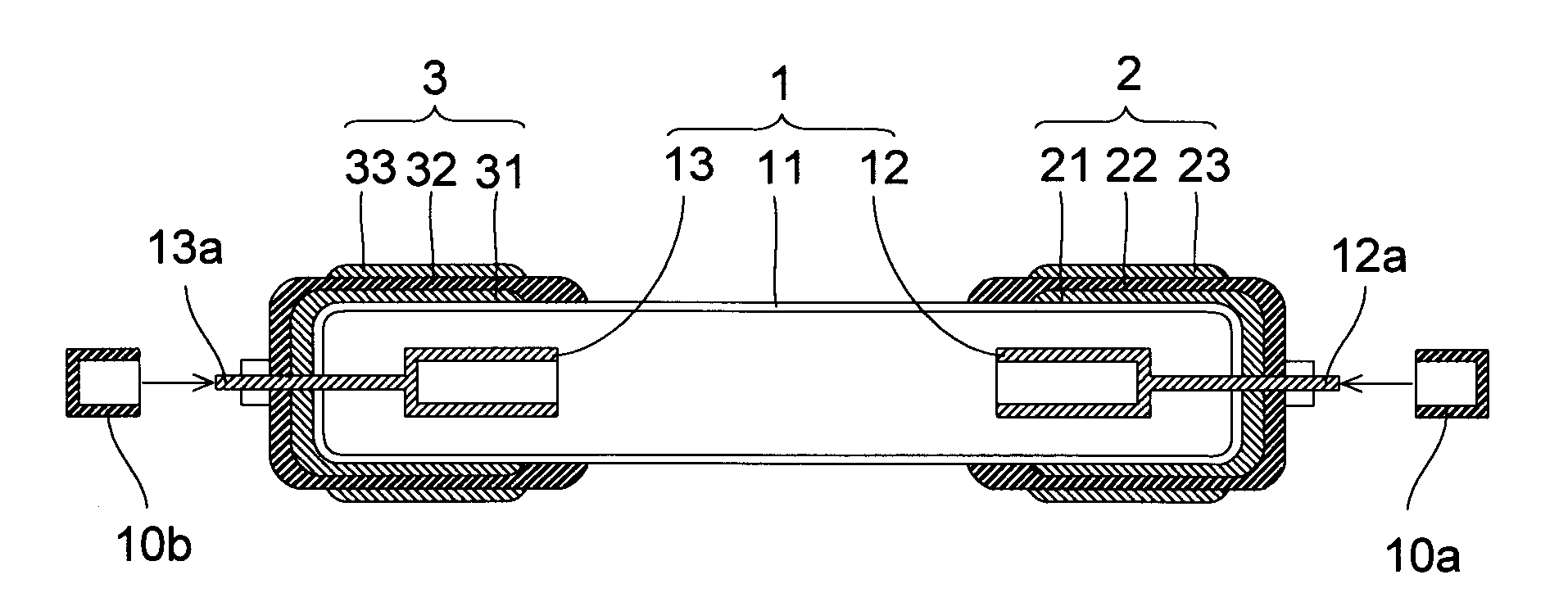
[0025]First, with reference to FIGS. 1 to 3, the structure of a cold cathode tube lamp according to a first preferred embodiment of the present invention will be described.

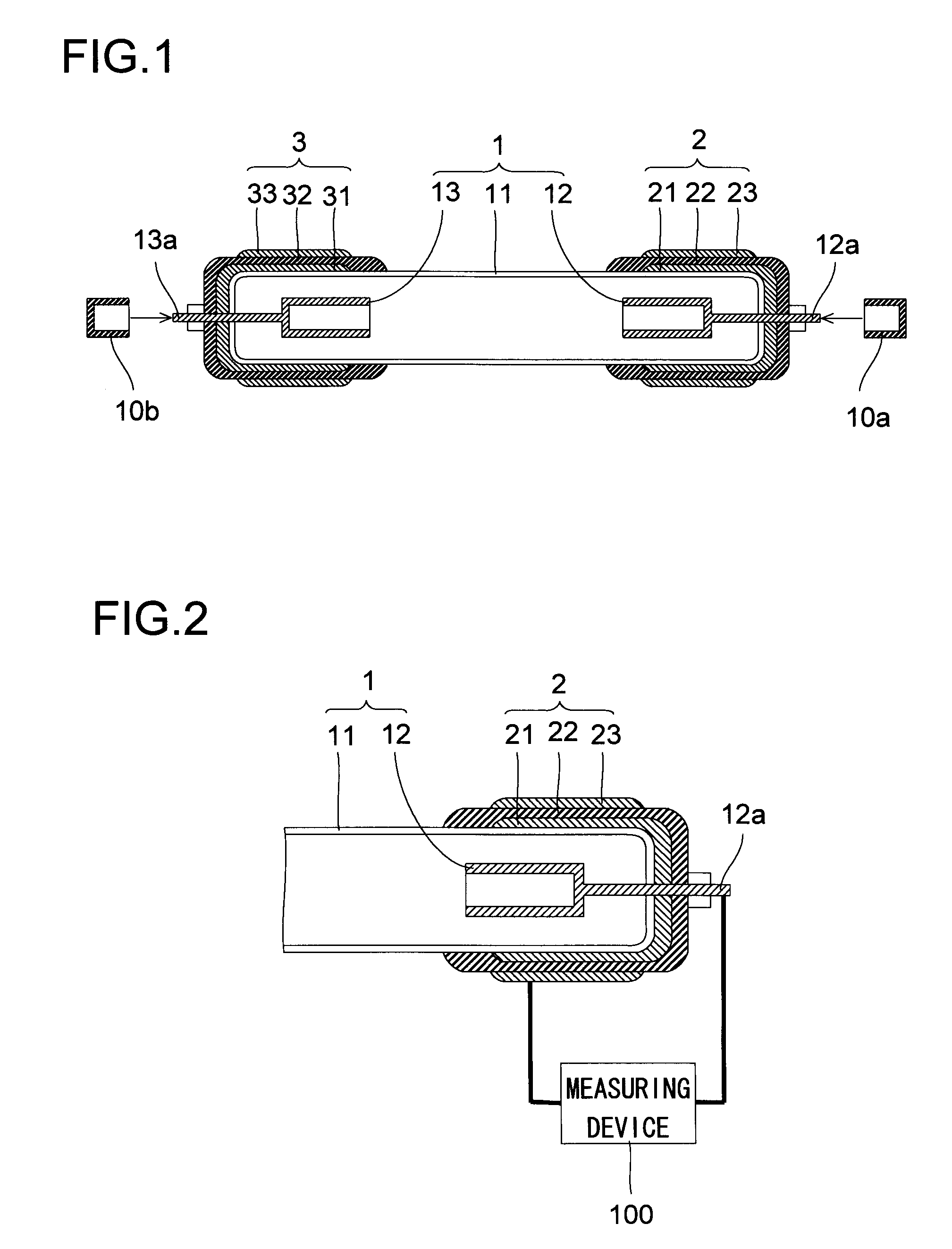
[0026]As shown in FIG. 1, the cold cathode tube lamp according to the first preferred embodiment is provided with a discharge tube 1 composed of a hermetic cylindrical glass tube 11 and a pair of internal electrodes 12 and 13 provided inside the glass tube 11. Note that, though not shown, a fluorescent substance is applied on the inner wall surface of the glass tube 11, and rare gas (a mixed gas of Ne and Ar) and mercury vapor are sealed in the glass tube 11. The internal electrodes 12 and 13 are formed of tungsten, and are disposed in one and the other end parts, respectively, of the glass tube 11. Moreover, the internal electrodes 12 and 13 have lead terminal portions 12a and 13a, respectively.

[0027]At one and the other end parts of the discharge tube 1, ballast capacitors 2 and 3, respectively are provided inte...

second preferred embodiment

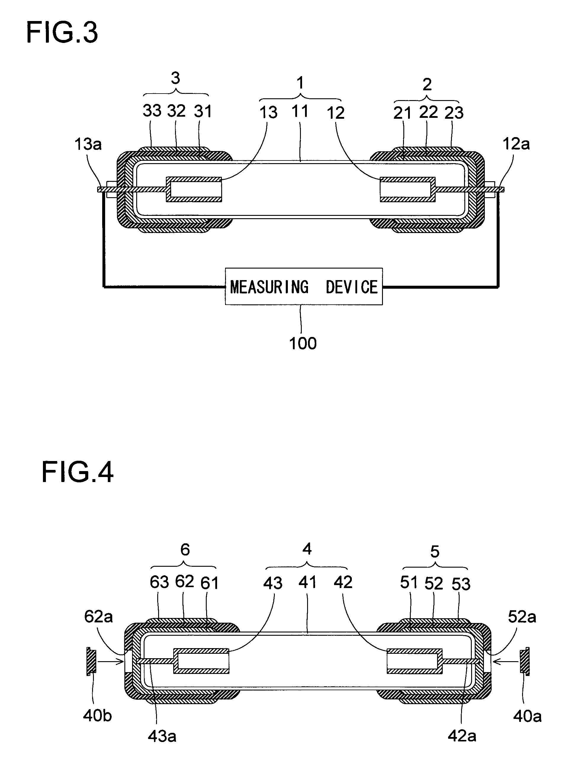
[0037]Next, with reference to FIGS. 4 and 5, the structure of a cold cathode tube lamp according to a second preferred embodiment of the present invention will be described.

[0038]As shown in FIG. 4, a discharge tube 4 of the cold cathode tube lamp according to the second preferred embodiment has a structure like that of the discharge tube 1 according to the above-described first preferred embodiment, and is composed of a hermetic cylindrical glass tube 41 and a pair of internal electrodes 42 and 43 provided inside the glass tube 41. The internal electrodes 42 and 43 have lead terminal portions 42a and 43a, respectively.

[0039]At one and the other end parts of the discharge tube 4, ballast capacitors 5 and 6, respectively are provided integrally therewith. Specifically, the ballast capacitor 5 fitted at the one end part of the discharge tube 4 has a structure like that of the ballast capacitor 2 according to the above-described first preferred embodiment, and is composed of a cylindri...


PUM


Abstract

Disclosed is a cold cathode lamp composed of discharge tube having a glass tube and an internal electrode, and a ballast capacitor integrally mounted to the discharge tube. The ballast capacitor is composed of a first electrode formed on the outer surface of the discharge tube, a dielectric layer covering the first electrode, and a second electrode formed on the dielectric layer. The internal electrode and the first electrode are electrically connected with each other. At least one of the internal electrode and the first electrode has a portion exposed to the outside. The capacitance of the ballast capacitor can be measured by connecting the exposed portion and the second electrode to a measuring device. Consequently, variations in capacitance of the ballast capacitor, which cause variations in luminance of the cold cathode lamp, can be easily examined.

Description

BACKGROUND OF THE INVENTION[0001]1. Field of the Invention[0002]The present invention relates to a cold cathode tube lamp. In particular, the present invention relates to a cold cathode tube lamp that is provided with a ballast capacitor.[0003]2. Description of the Related Art[0004]Conventionally, cold cathode tube lamps are used as light sources for various devices. For example, conventionally, there are known cold cathode tube lamps that can be used as light sources (backlights) for liquid crystal display devices.[0005]Conventional cold cathode tube lamps are, in terms of an equivalent circuit, a resistor whose resistance decreases nonlinearly as current increases, and have a nonlinear negative impedance characteristic like the V-I characteristic shown in FIG. 6. Thus, when an attempt is made to drive a plurality of cold cathode tube lamps connected in parallel, there arises the following inconvenience. Specifically, when an attempt is made to drive a plurality of cold cathode tub...

Claims


Application Information

Patent Timeline
Patent Type & Authority Applications(United States)
IPC IPC(8): H01J61/56
CPCH01J65/046H01J61/56
Inventor IWAMOTO, KENICHI
Owner SHARP KK
Why Eureka
Try Eureka