Different aspects of electronic pens

Inactive Publication Date: 2010-04-08
ANOTO AB
View PDF21 Cites 130 Cited by
  • Summary
  • Abstract
  • Description
  • Claims
  • Application Information

AI Technical Summary

Benefits of technology

[0030]This aspect provides a simple and efficient way of adding functionality to a pen. The protective cap is likely to be regarded as an indispensable part of the electronic pen, and is thus naturally brought with the pen. A range of different caps may be provided, each adding it own functionality. Thereby, different functionality may be added to a pen by simply switching cap.
[0031]In one embodiment, said means comprises at least one of a radiation source provi

Problems solved by technology

Since these components are both numerous and small, assembly work may be difficult and time-consuming.
Even minor changes in pen design and/or use may thus result in extensive development work to adapt the camera.
If the pen is used for writing, the movement of the stylus may impair the user's writing experience.
Further, unless special care is taken t

Method used


Image

  • Different aspects of electronic pens
  • Different aspects of electronic pens
  • Different aspects of electronic pens

Examples


Example

General

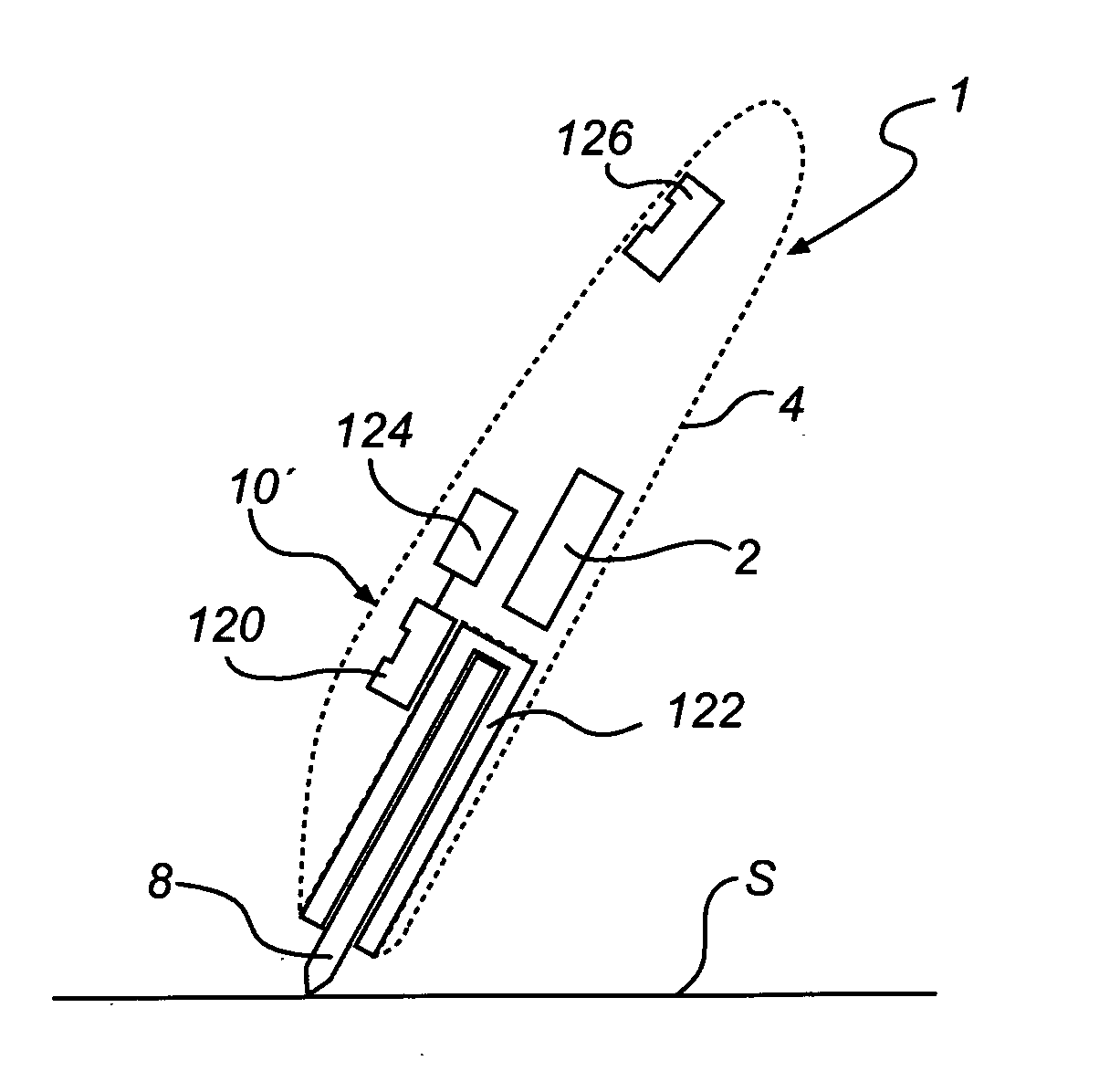
[0060]The following description revolves around different aspects of electronic pens. Generally speaking, an electronic pen 1 comprises data capturing circuitry 2 enclosed in a pen-shaped casing 4, as illustrated in FIG. 1. The pen may or may not also include a data transmitter 3, a processor 5 for further processing of the captured data, a memory 6 for data storage, an internal power source 7, such as a battery, and a stylus 8 for pointing to a product surface S, and optionally for marking the surface.

[0061]The pen may further comprise a pen down detector (PDD) 10, which generates a signal indicating that the pen 1 is in an operative position relative to the product surface S. The signal from the PDD 10 may selectively activate the data capturing circuitry 2 and / or the processor 5 and / or the transmitter 3, thereby reducing the power consumption of the pen since major power-consuming components are only fully activated when the pen is in the operative position. The PDD 10 is ...


PUM


Abstract

A miniaturized optical component (36) for a camera pen has the shape of a plate and comprises at least two non-overlapping radiation-transmitting sections: an imaging section (36′) configured to transmit an image of an object plane, and an illuminating section (36″) configured to transmit illuminating radiation towards the object plane. Passive optical elements may be incorporated in the component to provide the imaging and illuminating sections, e.g. an image-generating surface structure, an illumination-controlling surface structure, a radiation filter, a stray light shield, and an aperture stop. These optical elements may be provided as well-defined surface structures and layers on a plate substrate. The optical component may be manufactured as a wafer structure comprising a plurality of these optical components. A camera housing (22) may be provided with a first mounting structure (56) for the optical component (36), a second mounting structure (64) for an image sensor (11) configured to detect the image, and a third mounting structure (66) for a radiation source (13) configured to generate the illuminating radiation. An elongate guide pipe (24) for receiving a stylus (8) may be received in and joined to an elongate recess (28) in an exterior wall portion of the camera housing (22).

Description

CROSS-REFERENCE TO RELATED APPLICATIONS[0001]The present application claims the benefit of Swedish patent application no. 0700785-9, filed on Mar. 28, 2007, and U.S. provisional patent application No. 60 / 907318, filed on Mar. 28, 2007, both of which are hereby incorporated by reference.FIELD OF THE INVENTION[0002]The present invention relates to improvements in electronic pens in general, and to camera pens in particular.BACKGROUND OF THE INVENTION[0003]Camera pens are known to include a miniaturized camera for capturing images of a product surface, see e.g. US2004 / 0179000, WO2005 / 057471 and US2003 / 0075673.[0004]Generally, the camera is designed as a package of a large number of separate components, such as a CCD sensor, one or more imaging lenses, an aperture stop, a radiation filter, an illuminating LED, optics for redirecting / shaping the illuminating radiation emitted from the LED, etc. Since these components are both numerous and small, assembly work may be difficult and time-co...

Claims


Application Information

Patent Timeline
IPC IPC(8): H04N5/222H04N5/225G06F3/033G06F3/0354G06V10/12
CPCG06F3/0317G02B13/0085G06K9/24G06F3/03545G06F3/0321G06V10/12G06F3/0354
Inventor CRAVEN-BARTLE, THOMAS
Owner ANOTO AB
Why Eureka
Try Eureka