
Keyboard set having a micro projector

a projector and keyboard technology, applied in the field of keyboard sets, can solve the problems of inconvenience for moving, unusable and inconvenient arrangement of lines, etc., and achieve the effect of saving spa

Active Publication Date: 2010-04-08
CORETRONIC
View PDF16 Cites 11 Cited by
  • Summary
  • Abstract
  • Description
  • Claims
  • Application Information

AI Technical Summary

Benefits of technology

[0015]The embodiment or embodiments of the invention may have at least one of the following advantages: A. reducing the signal lines of desktop computer devices; B. integrating the peripheral units into the keyboard set for using more conveniently; C. users may select position of the computer freely in the scope that the wireless or wired transmission unit may receive signals by carrying the keyboard set.

Problems solved by technology

When these lines are scattered on the desk, it is unsightly and also inconvenient to arrange these lines.
Although the liquid crystal display (LCD) is very popular nowadays, the LCD is still bulky and has to be connected to the host 110, and thus bringing inconvenience for moving.

Method used


Image

  • Keyboard set having a micro projector
  • Keyboard set having a micro projector
  • Keyboard set having a micro projector

Examples


Embodiment Construction

[0024]In the following detailed description of the present embodiments, reference is made to the accompanying drawings which form a part hereof, and in which are shown by way of illustration specific embodiments in which the invention may be practiced. In this regard, directional terminology, such as “top,”“bottom,”“front,”“back,” etc., is used with reference to the orientation of the Figure(s) being described. The components of the present invention can be positioned in a number of different orientations. As such, the directional terminology is used for purposes of illustration and is in no way limiting. On the other hand, the drawings are only schematic and the sizes of components may be exaggerated for clarity. It is to be understood that other embodiments may be utilized and structural changes may be made without departing from the scope of the present invention. Also, it is to be understood that the phraseology and terminology used herein are for the purpose of description and ...


PUM


Abstract

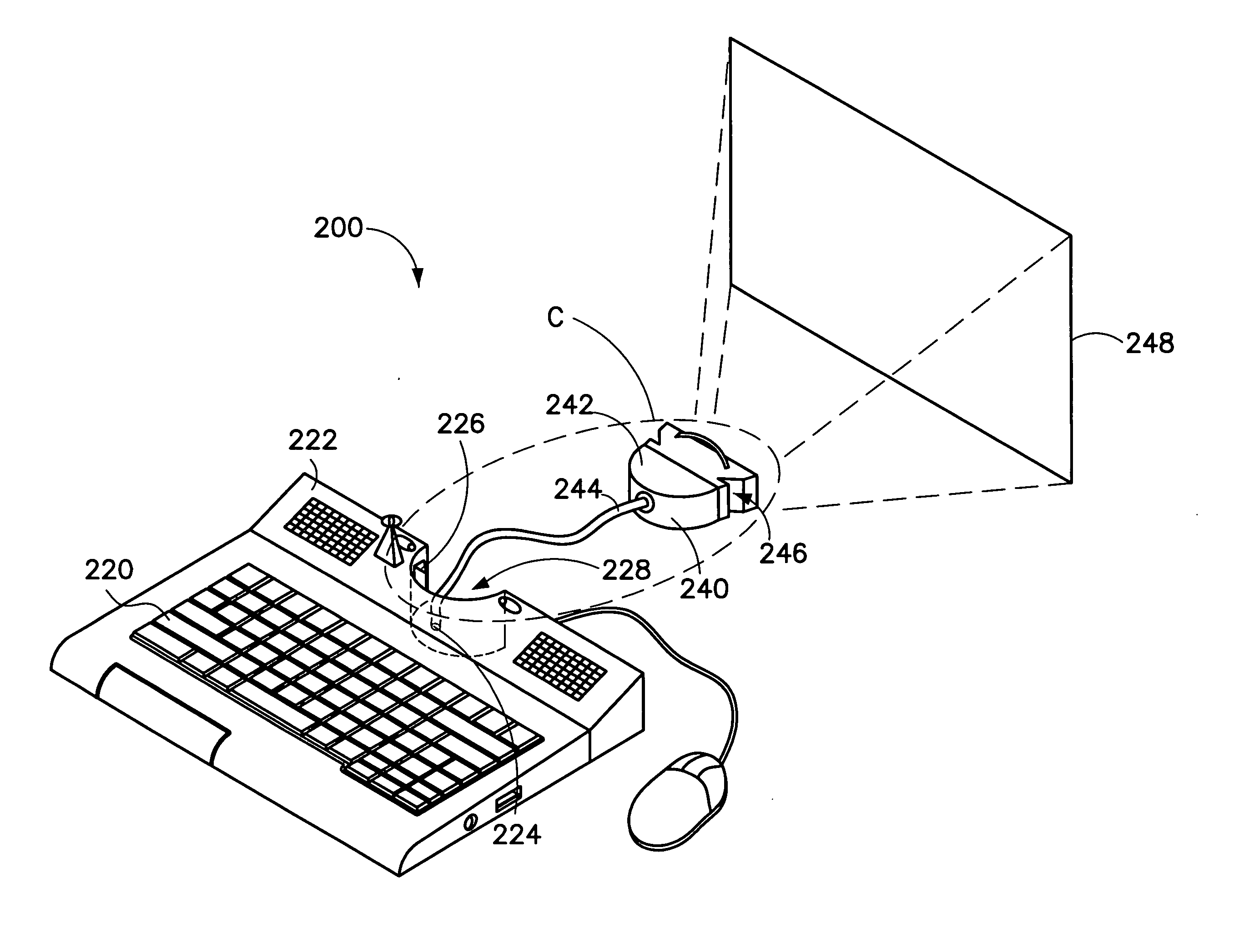
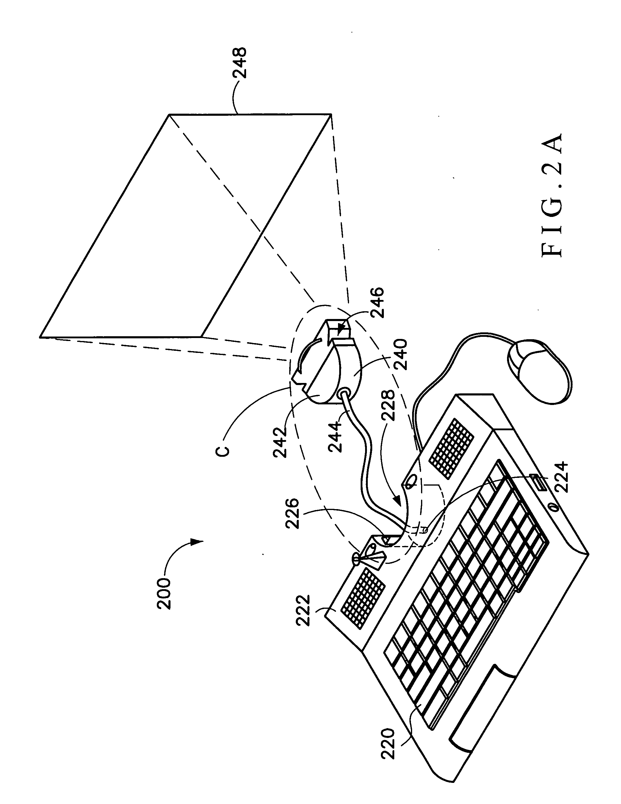
A keyboard set includes a keyboard unit, and a micro projector. The keyboard unit has a first housing, a video signal port and a first lock structure. The video signal port and the first lock structure are disposed in the first housing. The micro projector has a second housing, a signal line, and a second lock structure. The signal line is connected to the video signal port of the keyboard unit. The second lock structure is disposed on the second housing, and capable of combining with the first lock structure, for the micro projector to be fixed to the keyboard unit.

Description

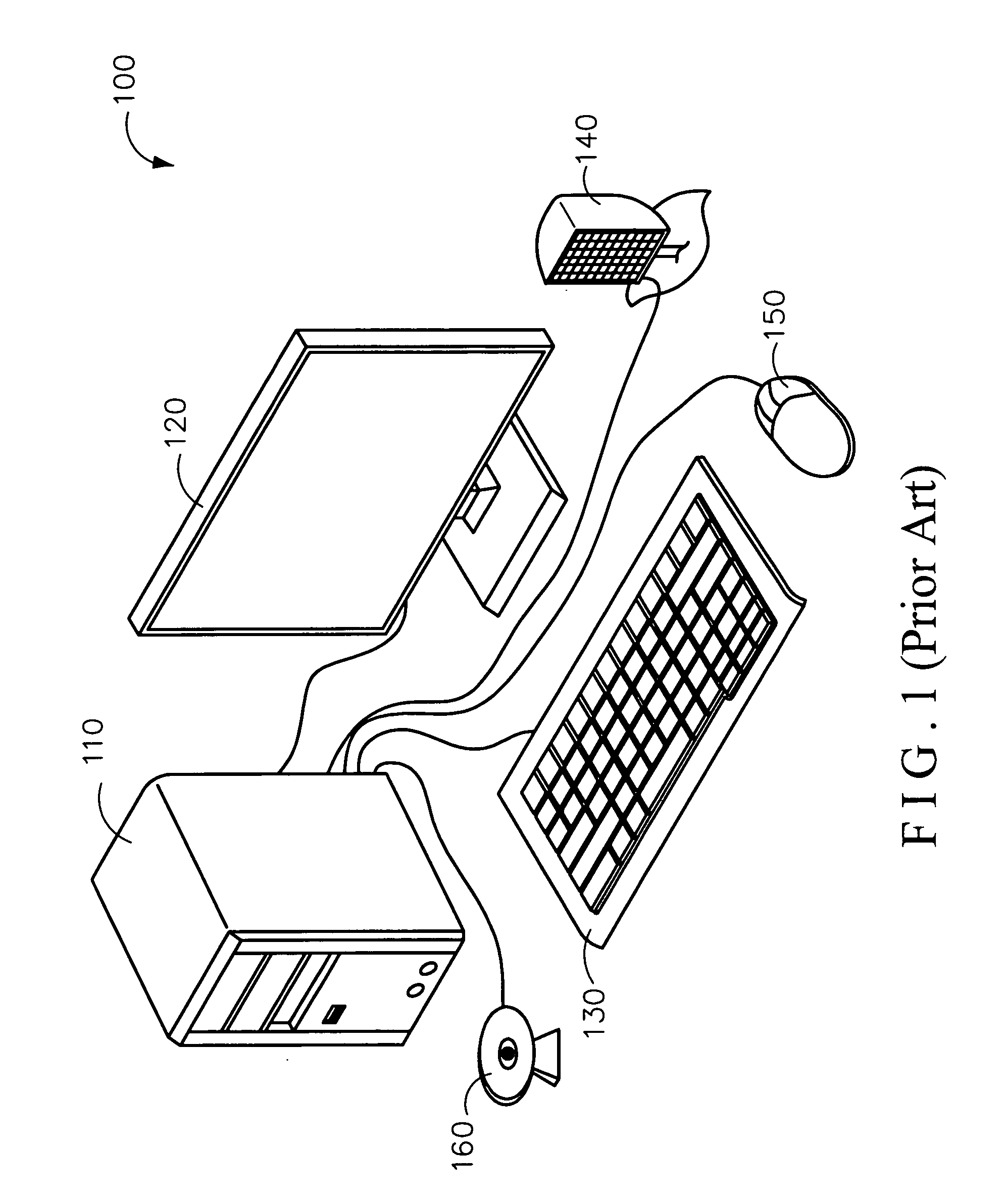
BACKGROUND OF THE INVENTION[0001](1) Field of the Invention[0002]The invention relates to a keyboard set, and more particularly relates to a keyboard set with projecting function.[0003](2) Description of the Related Art[0004]With progress of the times, computer device focuses on multimedia function, and the interface device of the computer device tends to be diversified.[0005]Refer to FIG. 1 for a schematic view of a conventional desktop computer device 100. The desktop computer device 100 usually has a host 110, a screen 120, a keyboard 130, a horn 140, a mouse 150, and a video camera 160. As FIG. 1 shows, each of the peripheral devices connects and communicates with the host 110 via a signal line (not shown).[0006]However, all peripheral devices applied in the conventional computer device 100 are connected to the host 110 by signal lines. More peripheral devices need more signal lines. When these lines are scattered on the desk, it is unsightly and also inconvenient to arrange the...

Claims


Application Information

Patent Timeline
Patent Type & Authority Applications(United States)
IPC IPC(8): G06F1/16
CPCG06F3/021
Inventor YIN, NAN-JIUNTSAI, MING-LUNG
Owner CORETRONIC
Learn More