Apparatus for optical body analysis

a technology of optical body and apparatus, applied in the field of medical devices, can solve the problems of little mechanical strength, and achieve the effects of safer and lower cost, more accurate measurements, and shorter measurement times

Inactive Publication Date: 2010-04-08
KONINKLIJKE PHILIPS ELECTRONICS NV
View PDF15 Cites 4 Cited by
  • Summary
  • Abstract
  • Description
  • Claims
  • Application Information

AI Technical Summary

Benefits of technology

[0009]In an examplary embodiment, the optical coupler is made out of a light weight material. In a particular embodiment, the illumination and detection head further comprises lens(es) arranged in front of the detector to selectively collect light emerging with respect to an area of interest allowing more accurate measurements or shorter measurement times.
[0010]In another embodiment, a lens is placed in front of the light source to project the light to the desired area to measure. The lens allows using an extended light source, such as a bulb, rather than a point source, e.g. as a laser, allowing for a safer and lower cost device.
[0011]In another embodiment, the light source and the detector are positioned in order to prevent light reflected directly by the optical coupler to enter the detector. This way, only light diffusely reflected by the sample enters the detector. As the light that has been directly reflected off the optical coupler contains no valuable information, this embodiment improves the measurement signal-to-noise ratio. This advantage can also be achieved in another embodiment where each of the light source and the detector comprises a polarizer, the polarization direction of one polarizer being orthogonal to the polarization direction of the other polarizer.

Problems solved by technology

Indeed, contrary to prior art systems, only the optical coupler is placed on the body portion, e.g. skin surface, and there is little mechanical strength between the optical coupler and the illumination and detection head when such mechanical strength would constrain the head onto the optical coupler.

Method used


Image

  • Apparatus for optical body analysis
  • Apparatus for optical body analysis
  • Apparatus for optical body analysis

Examples


Embodiment Construction

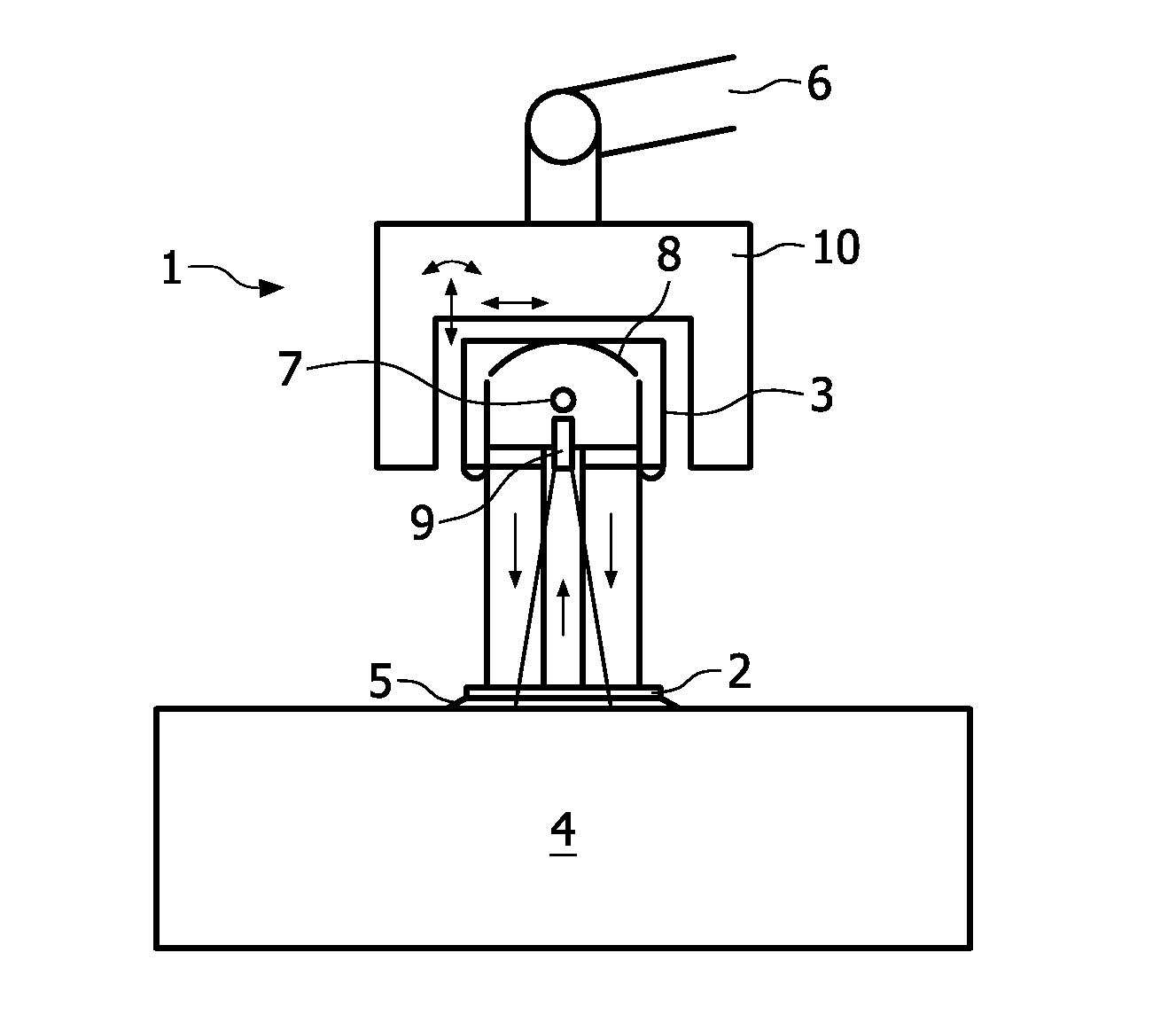
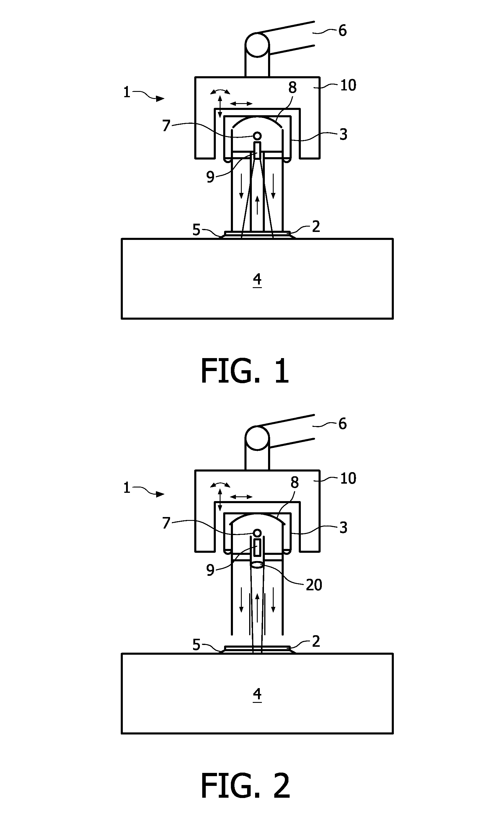
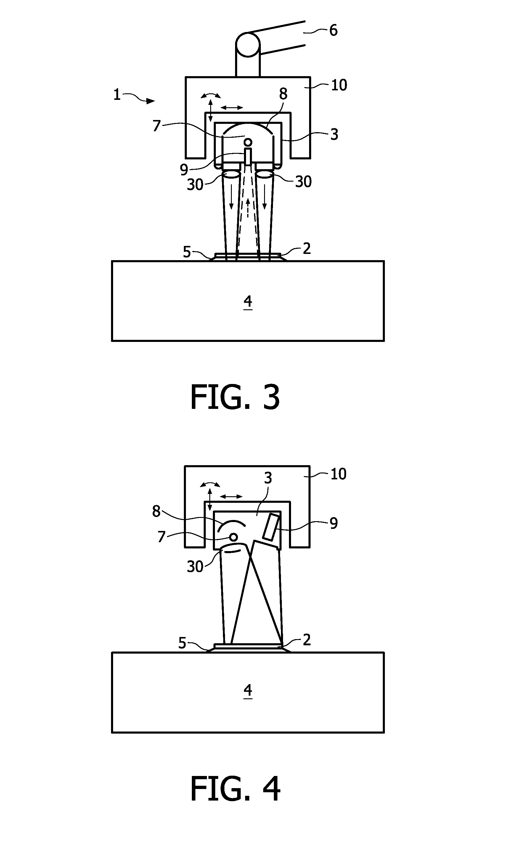
[0024]In reference to FIG. 1, an apparatus 1 comprises an optical coupler 2 and an illumination and detection head 3.

[0025]The optical coupler 2 is positioned on the outer layer of the body portion 4 to analyze. The outer layer is for example the patient's skin. Optical coupler 2 may be a piece of transparent material with a well defined smooth surface. Optical couplers are typically used to correct for the skin roughness so that the relief of the illuminated surface is known when the skin is illuminated. This makes it easier to predict how much light is reflected and how much light penetrates the skin. Optical coupler 2 can also be either associated with an index matching fluid or gel 5 that is placed between optical coupler 2 and the skin 4 to prevent any air bubbles being trapped at the interface skin-coupler. The index matching fluid 5 minimizes reflection of light passing through optical coupler 2 and the skin 4 or at the interface between the two. The fluid or gel 5 could also...


PUM

PropertyMeasurementUnit
refractive indexaaaaaaaaaa
optical body analysisaaaaaaaaaa
pressureaaaaaaaaaa

Abstract

An apparatus for optical body analysis is built with an illumination and detection head, and an optical coupler. The illumination and detection head comprises a light source for illuminating a body portion to analyze through the optical coupler and a detector for receiving light diffusely reflected by the body portion. The optical coupler is mechanically decoupled from the illumination and detection head and is adapted to be in contact with an outer surface of the body portion while the contact between the optical coupler and the body portion minimally affects physical properties of the body portion. The apparatus may further comprise a position unit adapted to adjust the position of the illumination and detection head relative to the optical coupler so that the detector receives through the optical coupler light generated by the light source and diffusely reflected by the body portion.

Description

FIELD OF THE INVENTION[0001]The invention relates to the field of medical apparatus and more specifically to an apparatus for the optical analysis of body portions such as the lower skin layers. The invention is particularly relevant to the field of non-invasive optical skin analysis for the detection of skin layers properties and components.BACKGROUND OF THE INVENTION[0002]Optical measurement of the skin of a patient is often used to detect biological parameters. For instance, Near Infra-Red (NIR) spectroscopy is a non-invasive method for determining glucose concentration in tissue and blood. NIR spectroscopy is often used in diabetes glucose control. It operates as follows: first, a light source illuminates a body portion with NIR light via an optical probe head in contact with skin and light reflected by the body fluids and body tissue is then detected in the probe head.[0003]Patent application JP06-052444 discloses, for instance, a device used to observe an enlarging surface of ...

Claims


Application Information

Patent Timeline
Patent Type & Authority Applications(United States)
IPC IPC(8): A61B6/00G01J4/00G01N21/47
CPCA61B5/0059A61B2562/146A61B5/6843A61B5/441
Inventor LUCASSEN, GERHARDUS WILHELMUSRENSEN, WOUTER HARRY JACINTH
Owner KONINKLIJKE PHILIPS ELECTRONICS NV
Why Eureka
Try Eureka