Acoustic reflectometry instrument and method

Inactive Publication Date: 2010-04-08
INNOVIA MEDICAL LTD
View PDF0 Cites 1 Cited by
  • Summary
  • Abstract
  • Description
  • Claims
  • Application Information

AI Technical Summary

Benefits of technology

[0006]The present invention is directed to an acoustic reflectometry instrument and method employing improved techni

Problems solved by technology

While instruments have been developed and used successfully based on acoustic reflectometry, they have not been wholly without problems.
The relatively high cost of the instruments has been a notable disadvantage.
In particular, expensive microphones and speakers have been

Method used


Image

  • Acoustic reflectometry instrument and method
  • Acoustic reflectometry instrument and method
  • Acoustic reflectometry instrument and method

Examples


Embodiment Construction

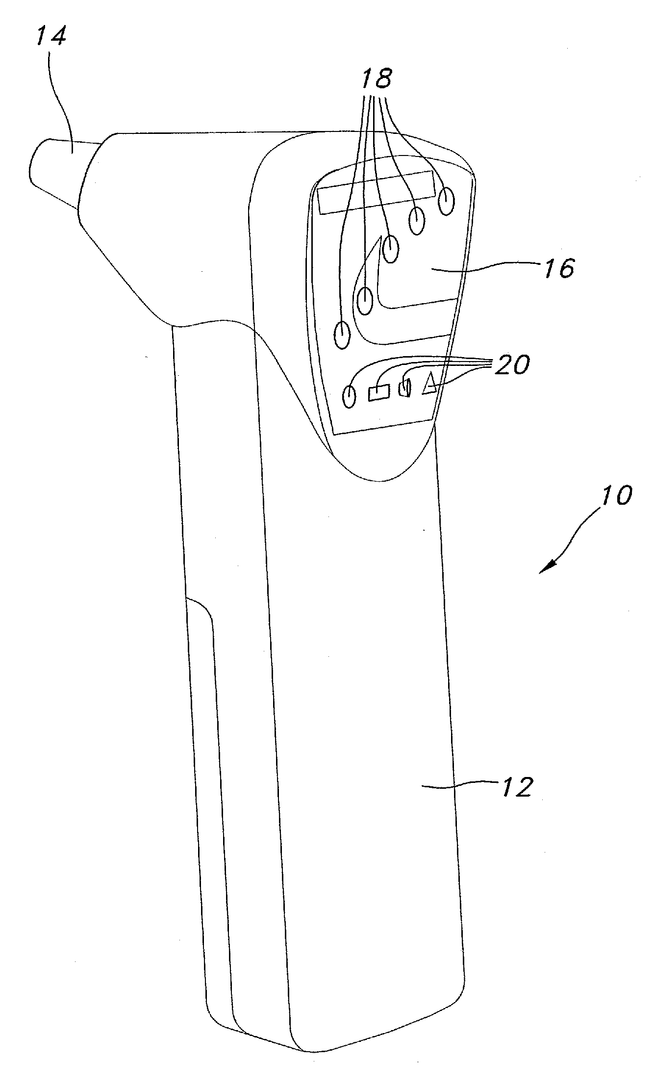
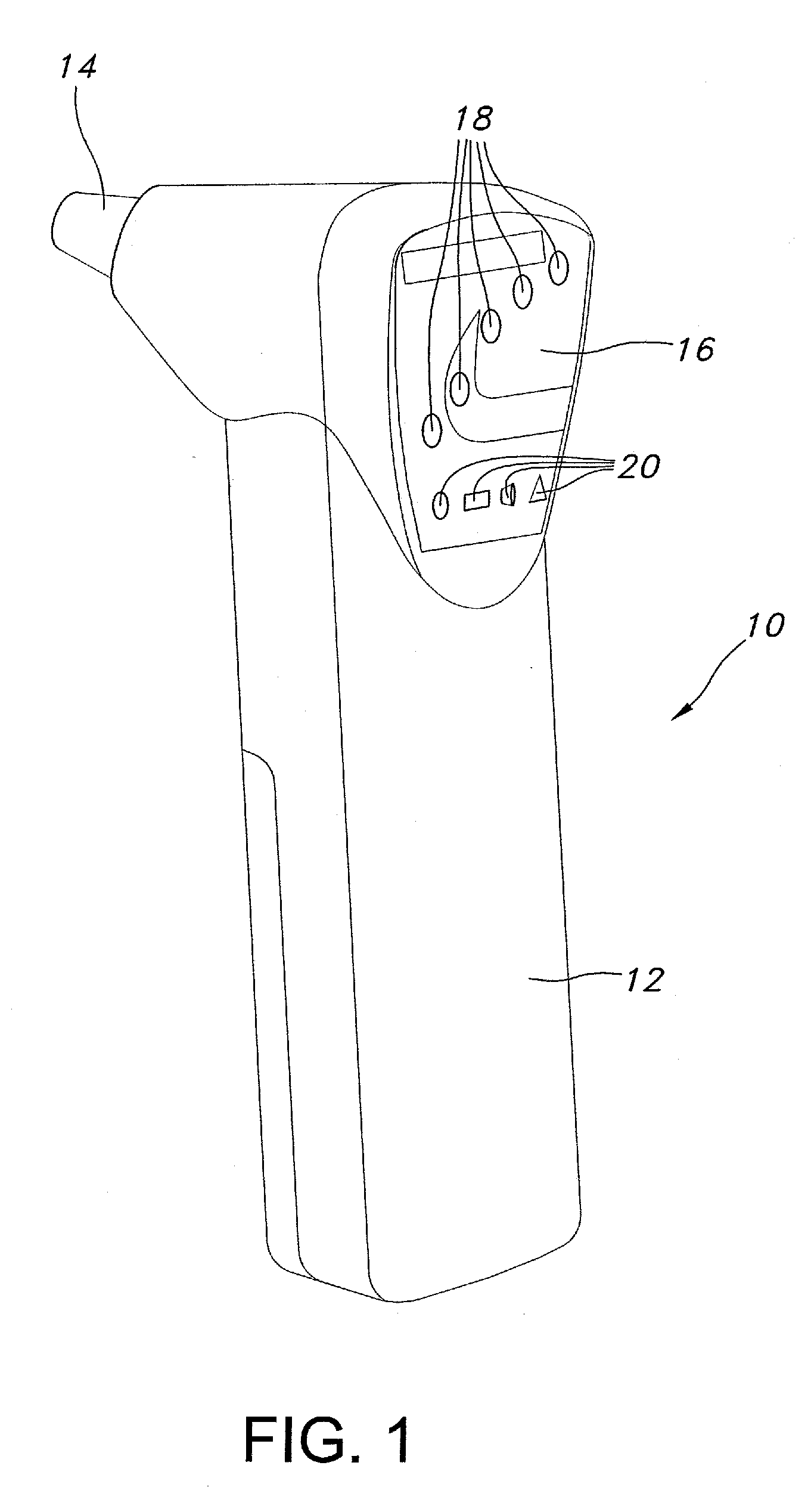
[0016]Referring now to the drawings in more detail and initially to FIG. 1, the present invention is directed to the use of acoustic reflectometry for evaluation and diagnosis of the ear. The invention may be implemented using an instrument which is generally identified by numeral 10 and which may be a handheld device having a handle 12. The head end of the instrument 10 is provided with a tip 14 having a size and shape to be inserted into an ear that is to be diagnosed. The head of the instrument may also be provided with a panel 16 having various control components and displays which may include a number of LED indicators 18 and other indicators 20.

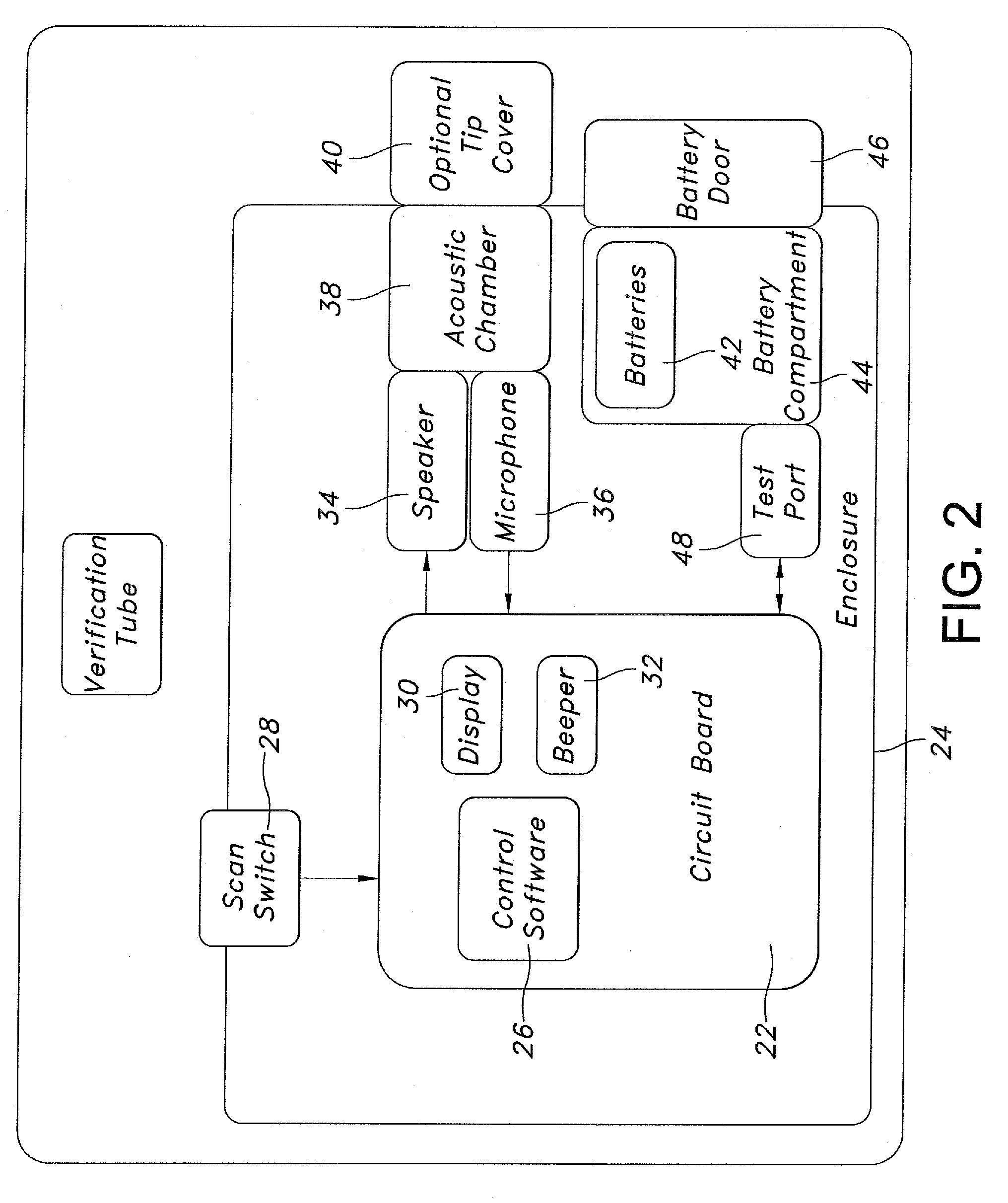
[0017]FIG. 2 depicts diagrammatically the principal components of the instrument 10. A circuit board 22 within the enclosure or housing 24 of the instrument controls its operation using control software 26. A scan switch 28 may be activated to initiate a measurement. A display 30 and beeper 32 or other audible device may be included and...


PUM


Abstract

An acoustic reflectometry instrument and method for ascertaining fluid presence in an ear. Drive side normalization involves normalizing the speaker to adjust its output to compensate for non-linearity over a frequency range used for acoustic reflectometry measurement of the ear. The microphone is normalized to compensate for system non-linearity. Measurement involves repetition a selected number of times until the spectral gradient angle is within a specified range for each repetition to provide validation of the measurement. For enhanced reliability, various sources of error are tested.

Description

CROSS-REFERENCE TO RELATED APPLICATIONS[0001]None.FIELD OF THE INVENTION[0002]This invention relates generally to the field of acoustic reflectometry and deals more particularly with a method and apparatus making use of acoustic reflectometry for evaluation of the ear to detect the presence of fluid which may be an indication of Otitis Media.BACKGROUND OF THE INVENTION[0003]Acoustic reflectometry is known to be useful in detecting the presence of fluid in the middle ear cavity. Excessive fluid levels may be an indication of Otitis Media or other afflictions. Acoustic reflectometry techniques typically involve propagating an audio signal at a number of frequencies through the ear canal. The reflected energy may be analyzed using known processes to determine the mechanical resonance characteristics of the ear drum. The shape of the frequency response curve is used to determine a spectral gradient angle which is a measurement of the characteristics of a null in the spectral curve.[0004...

Claims


Application Information

Patent Timeline
IPC IPC(8): A61B5/00
CPCA61B5/0048A61B2560/0209A61B5/121A61B5/0051
Inventor WARNER, DAVID P.
Owner INNOVIA MEDICAL LTD
Why Eureka
Try Eureka