Method for operating a working machine and a working machine

a technology of working machine and working machine, which is applied in the direction of data processing management, climate sustainability, electric energy vehicles, etc., can solve the problems of low power supply of combustion engines, inability to fully consume power provided by combustion engines, and high undesired impression of engine weakness, so as to reduce the performance of sub-systems and/or torque, flexible and compact design, and reduce the effect of power requiring sub-systems

a technology of working machine and working machine, which is applied in the direction of data processing management, climate sustainability, electric energy vehicles, etc., can solve the problems of low power supply of combustion engines, inability to fully consume power provided by combustion engines, and high undesired impression of engine weakness, so as to reduce the performance of sub-systems and/or torque, flexible and compact design, and reduce the effect of power requiring sub-systems

US20100089050A1Active Publication Date: 2010-04-15VOLVO CONSTR EQUIP

Image

  • Method for operating a working machine and a working machine
  • Method for operating a working machine and a working machine
  • Method for operating a working machine and a working machine

Examples


Embodiment Construction

Structure of Preferred Embodiments

[0040]A Working Machine

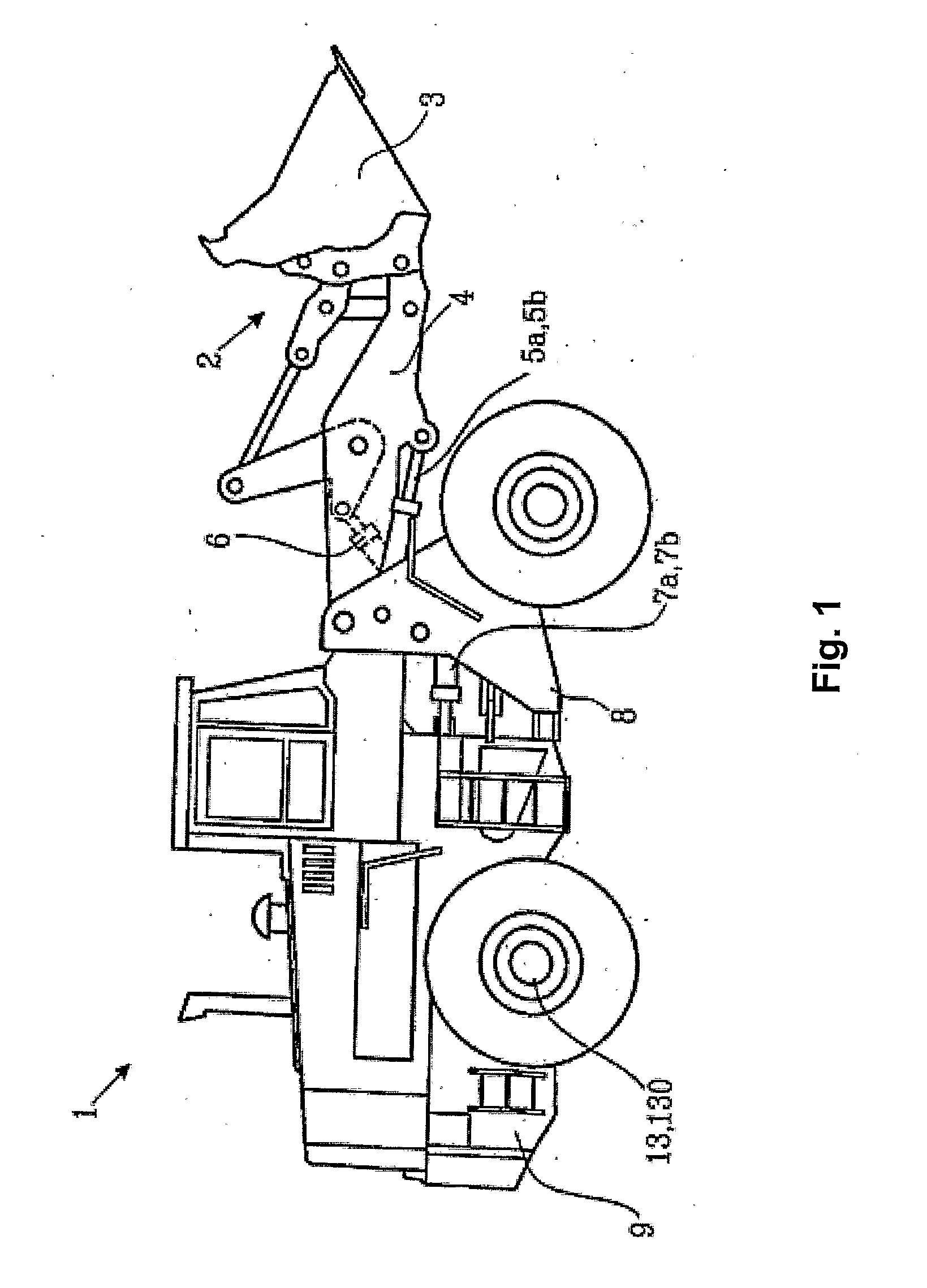
[0041]FIG. 1 is an illustration of an exemplifying working machine in the form of a wheel loader 1 having an implement 2 in the form of a bucket 3. The bucket 3 is arranged on an arm unit 4 for lifting and lowering the bucket 3. The bucket 3 can also be tilted or pivoted relative to the arm unit 4. For this purpose the wheel loader 1 is provided with a working hydraulic system 140 comprising at least one hydraulic pump (not shown in FIG. 1) and working cylinders 5a, 5b, 6 for lifting and lowering of the arm unit 4, and for tilting or pivoting the bucket 3. In addition, the working hydraulic system comprises working cylinders 7a, 7b for turning the wheel loader 1 by means of relative movement of a front body 8 and a rear body 9. These features of the wheel loader 1 and variations thereof are well known to those skilled in the art and they need no further explanation.

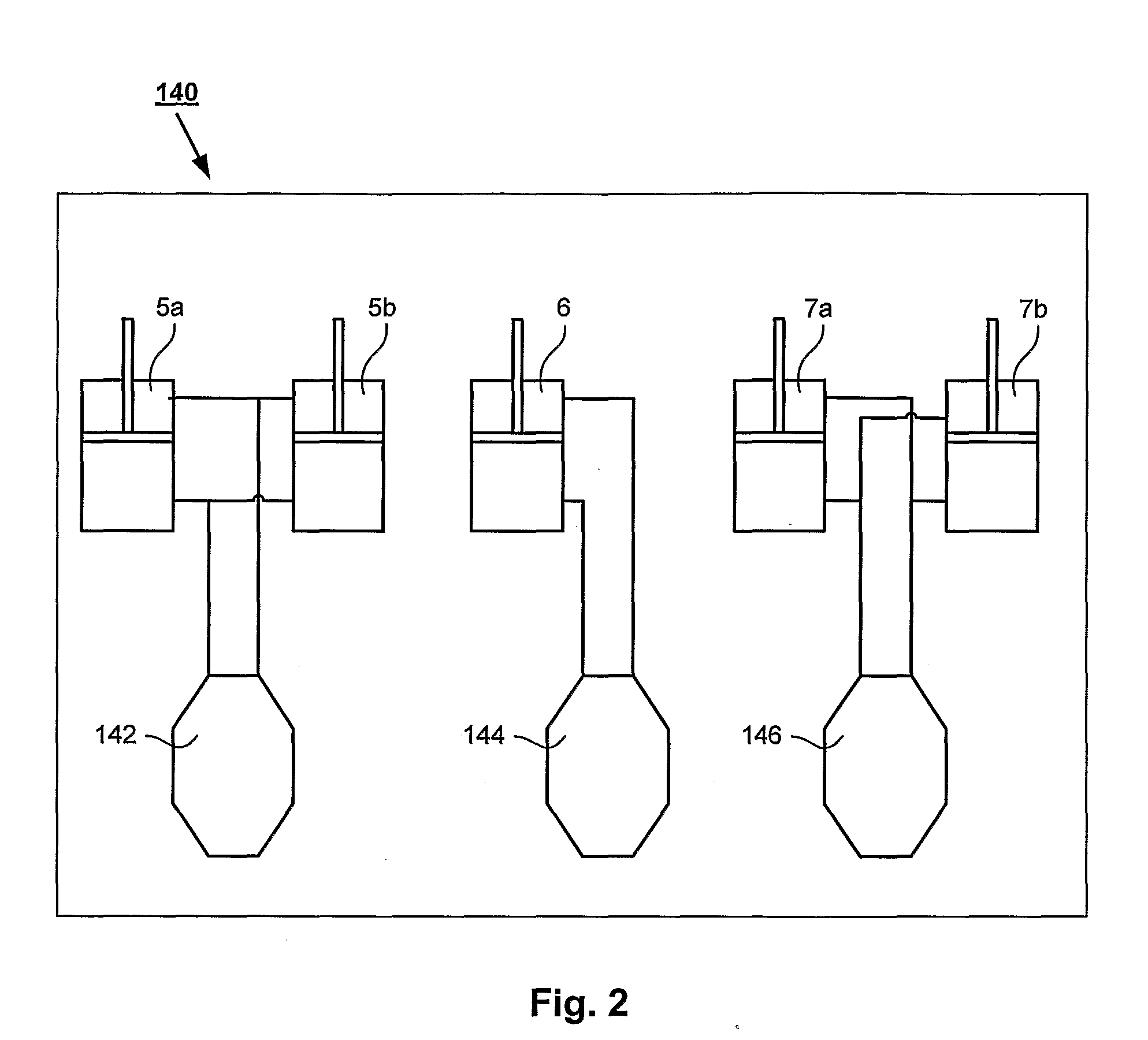
[0042]A Hydraulic System

[0043]FIG. 2 is a schematic illustrati...


PUM


Abstract

A method for operating a working machine provided with a power source providing power and a plurality of power consuming systems connected to the power source includes the steps of providing a model predicting a power demanded by at least one of the power consuming systems, detecting at least one operational parameter indicative of a power demand, using the detected operational parameter in the prediction model, and balancing a provided power to the demanded power according to the prediction model.

Description

BACKGROUND AND SUMMARY[0001]The invention relates to a method for operating a working machine and a working machine.[0002]The invention is applicable on working machines within the field of industrial construction machines, in particular wheel loaders. Thus, the invention will be described with respect to a wheel loader. However, the invention is by no means limited to a particular working machine. On the contrary, the invention may be used in a plurality of heavy working machines, e.g. articulated haulers, trucks, bulldozers and excavators.[0003]Wheel loaders are generally provided with an internal combustion engine, a transmission line, a gearbox, driving wheels and a working hydraulic system.[0004]The combustion engine provides power to the different functions of the wheel loader. In particular, the combustion engine provides power to the transmission line and to the working hydraulic system of the wheel loader.[0005]The transmission line transfers torque from the combustion engi...

Claims


Application Information

Patent Timeline
15 Apr 2010
Publication
US20100089050A1
IPC
F16D31/02
CPC
E02F9/2292; B60L2270/12; Y02T10/642; Y02T10/84; B60K6/48; B60L2240/425; B60W10/08; B60W10/20
Inventors
FILLA, RENO