Ventilated bicycle handlebar

Inactive Publication Date: 2010-04-15
SELLE ROYAL SPA
View PDF9 Cites 4 Cited by
  • Summary
  • Abstract
  • Description
  • Claims
  • Application Information

AI Technical Summary

Benefits of technology

[0017]Thus, both configurations will afford maximum g

Problems solved by technology

Nevertheless, extensive riding, particularly in competitions, or riding in particular high temperature conditions can lead to excessive hand perspiration, which can affect grip stability or even cause damage to the skin, e.g. skin blisters.
However, th

Method used


Image

  • Ventilated bicycle handlebar
  • Ventilated bicycle handlebar
  • Ventilated bicycle handlebar

Examples


Embodiment Construction

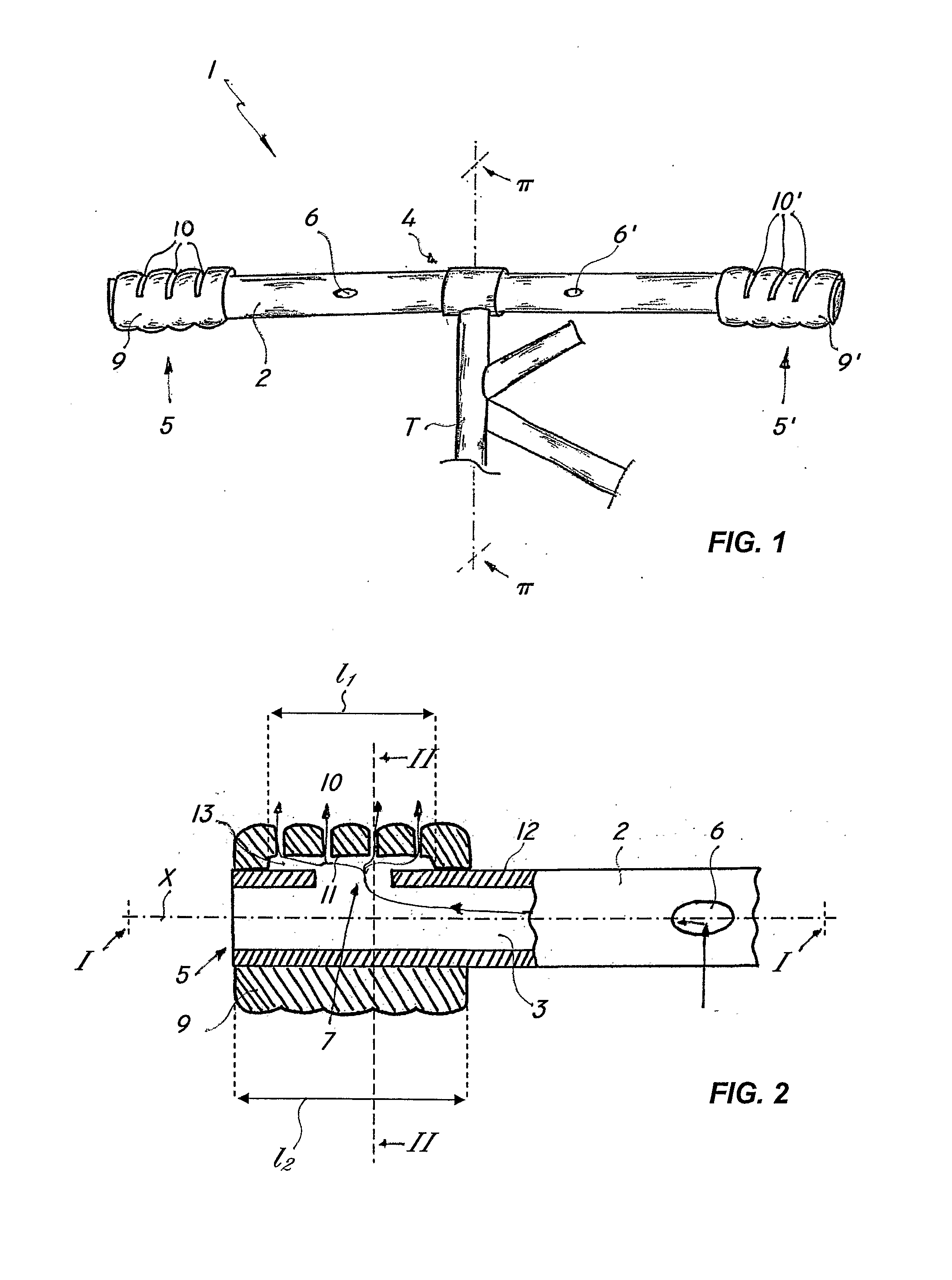
[0027]Referring to the above figures, the handlebar of the invention, generally designated with numeral 1, may be attached to a frame T of a bicycle and generally to any vehicle, even motor vehicles, having one or more front wheels steered by a handlebar.

[0028]The handlebar 1 may be formed of metal, plastic or composite material, such as carbon fiber or the like and may be attached to the frame in a permanent or removable manner.

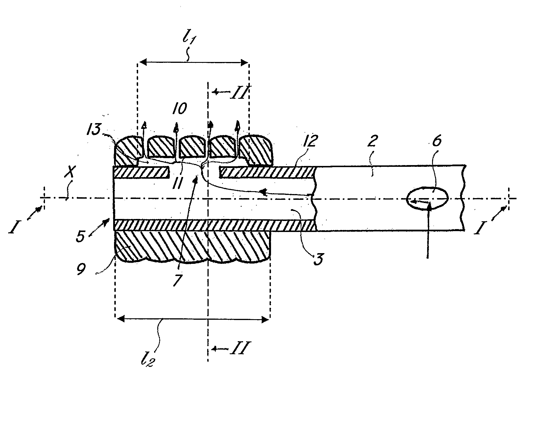
[0029]According to the invention, the handlebar 1 has a tubular body 2 having an axial inner cavity 3, a central portion 4 for connection to a bicycle frame T and end portions 5, 5′, designed to be grasped by the hands of a user.

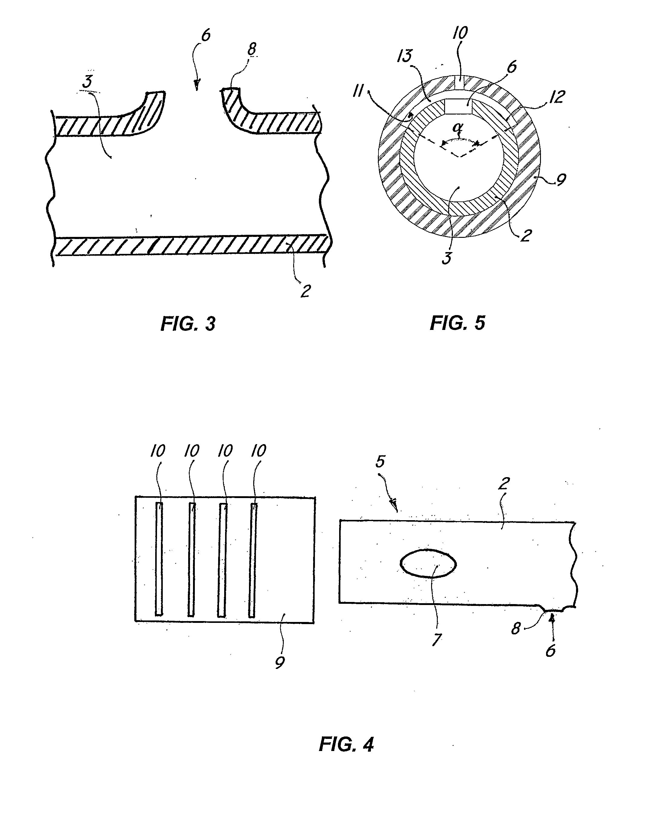
[0030]According to a peculiar feature of the invention, the tubular body 2 has at least one air inlet 6 near to its central portion 4 and at least one air outlet opening 7 in the remaining areas.

[0031]The inlet opening 6 is at least partly oriented in the vehicle advancement direction so that the incoming air can flow through the inn...


PUM


Abstract

The present invention finds application in the art of sport and leisure accessories, and relates to a ventilated bicycle handlebar, which includes a tubular body having an axial inner cavity, a center portion for connection to a bicycle frame and end portions, designed to be grasped by the hands of a user. The tubular body has an air inlet at the center portion and an air outlet in the remaining areas. The inlet is partly or wholly oriented in the riding direction so that the incoming air can flow through the inner cavity and come out of the outlet to ventilate the hands of a user during riding.

Description

FIELD OF THE INVENTION [0001]The present invention generally finds application in the technical field of sport and leisure accessories, and particularly relates to a tubular bicycle handlebar having holes for ventilating its handgrip portions.BACKGROUND OF THE INVENTION[0002]A bicycle handlebar is known to be formed of a tubular or solid bar which is mounted to the bicycle frame at its center portion and is designed to be grasped by the cyclist at its ends.[0003]Furthermore, handgrips or tapes of elastomeric materials, gels, leather or the like, for a safer and more comfortable grip by the cyclist, are usually applied to the gripping areas.[0004]U.S. Pat. No. 4,462,267 and US20030226420 disclose particular embodiments of bicycle handlebars.[0005]Nevertheless, extensive riding, particularly in competitions, or riding in particular high temperature conditions can lead to excessive hand perspiration, which can affect grip stability or even cause damage to the skin, e.g. skin blisters.[...

Claims


Application Information

Patent Timeline
IPC IPC(8): B62K21/12B62K21/26
CPCB62K21/12Y10T74/2078Y10T74/20828B62K21/26
Inventor LOSIO, MASSIMO
Owner SELLE ROYAL SPA
Why Eureka
Try Eureka