Geometry adaptive laser sintering system

a laser sintering and geometry technology, applied in the field of manufacturing, can solve the problems of large amount of powder that cannot be used and disposed, large amount of powder is often wasted during the build process, and large parts cannot be manufactured as quickly

Active Publication Date: 2010-04-15
THE BOEING CO
View PDF24 Cites 85 Cited by
  • Summary
  • Abstract
  • Description
  • Claims
  • Application Information

AI Technical Summary

Problems solved by technology

With currently used laser sintering machines, the powder used to create parts is often wasted during the build process.
However, a large amount of the powder is unusable and disposed of.
Thus, with currently available machines, larger parts cannot be manufactured as quickly.
Even further, with larger amounts of powder, differences in temperatures at different layers may result in parts that are warped or that do not meet tolerances.

Method used


Image

  • Geometry adaptive laser sintering system
  • Geometry adaptive laser sintering system
  • Geometry adaptive laser sintering system

Examples


Embodiment Construction

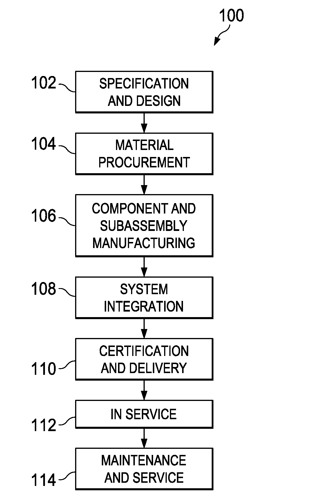
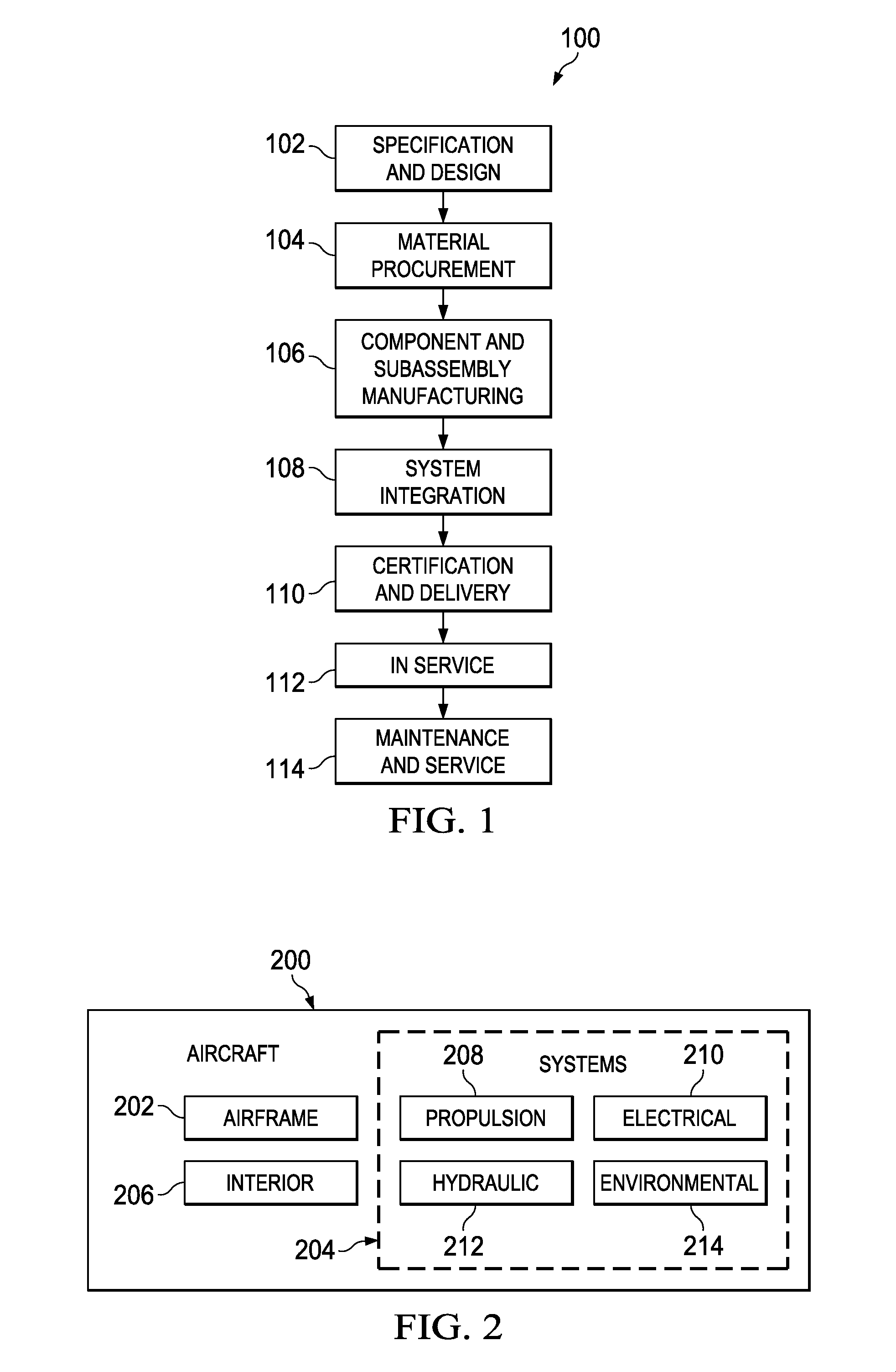
[0024]Referring more particularly to the drawings, embodiments of the disclosure may be described in the context of the aircraft manufacturing and service method 100 as shown in FIG. 1 and aircraft 200 as shown in FIG. 2. Turning first to FIG. 1, a diagram illustrating an aircraft manufacturing and service method is depicted in accordance with an advantageous embodiment. During pre-production, exemplary aircraft manufacturing and service method 100 may include specification and design 102 of aircraft 200 in FIG. 2 and material procurement 104.

[0025]During production, component and subassembly manufacturing 106 and system integration 108 of aircraft 200 in FIG. 2 takes place. Thereafter, aircraft 200 in FIG. 2 may go through certification and delivery 110 in order to be placed in service 112. While in service by a customer, aircraft 200 in FIG. 2 is scheduled for routine maintenance and service 114, which may include modification, reconfiguration, refurbishment, and other maintenance...


PUM

PropertyMeasurementUnit
temperatureaaaaaaaaaa
shapeaaaaaaaaaa

Abstract

An apparatus comprises a deformable platform and a laser delivery system. The deformable platform has a surface capable of changing to conform to a shape of an object as the object is being manufactured during a sintering process. The laser delivery system is capable of sintering powder on the deformable platform to manufacture the object.

Description

BACKGROUND INFORMATION[0001]1. Field[0002]The present disclosure relates generally to manufacturing and in particular, to a method and apparatus for manufacturing objects using laser sintering.[0003]2. Background[0004]Sintering is a process that may be used to make objects from powder. These objects include ceramic and / or metal objects. Sintering involves heating a material until the particles adhere to each other. With sintering, the material may be heated to a temperature that is below the melting point to provide for solid state sintering.[0005]Laser sintering is a type of sintering in which a high power laser is used to fuse particles into a mass representing a three-dimensional object. With this type of manufacturing process, the laser selectively fuses powdered material by scanning cross-sections of powder in a bed. These cross-sections are scanned based on a three-dimensional description of the object or part. This description may be obtained from various sources such as, for...

Claims


Application Information

Patent Timeline
Patent Type & Authority Applications(United States)
IPC IPC(8): B29C35/08
CPCB22F3/1055B29B13/007B29B13/021B29C35/045B29C67/0074B22F2003/1057B29C67/0088B29C2035/0838B29L2031/30B29L2031/3076B29C67/0077B29C64/153B29C64/141Y02P10/25B22F12/44B22F12/13B22F12/67B22F12/224B22F10/28B22F12/38B22F12/30
Inventor DIETRICH, DAVID MICHAELEASON, RICHARD L.
Owner THE BOEING CO
Why Eureka
Try Eureka