Engine starting apparatus

a technology for starting apparatuses and engines, applied in the direction of engine starters, electric devices, machines/engines, etc., can solve the problems of uncontrollable relays of starters, microcomputer resets, and drop in vehicle battery voltage, and achieve the effect of low cos

Active Publication Date: 2010-04-15
DENSO CORP
View PDF7 Cites 48 Cited by
  • Summary
  • Abstract
  • Description
  • Claims
  • Application Information

AI Technical Summary

Benefits of technology

[0021]According to the present invention, there is provided at low cost an engine starting apparatus capable of starting a vehicle engine even when its control means such as a microcomputer which operates on battery voltage supplied from a vehicle battery is disabled from operating due to drop of the battery voltage.

Problems solved by technology

Meanwhile, when the starter motor is started, since a large current flows through the starter motor because the starter motor has to generate large torque to rotate the crankshaft of the engine, the voltage of a vehicle battery drops.
Hence, there has been a risk that if the battery voltage drops excessively during normal engine start operation, the control-use voltage is lowered excessively, causing the microcomputer to be reset, and accordingly causing each relay of the starter to be uncontrollable.
As explained above, the techniques disclosed in the above patent documents in which the microcomputer included in the ECU individually controls the solenoid relay and the motor relay have the risk that the microcomputer is reset causing it to be unable to control these relays and accordingly causing it unable to start the engine, if the battery voltage drops excessively during the normal engine start operation.
However, providing such a voltage step-up circuit increases manufacturing costs.

Method used


Image

  • Engine starting apparatus
  • Engine starting apparatus
  • Engine starting apparatus

Examples


first embodiment

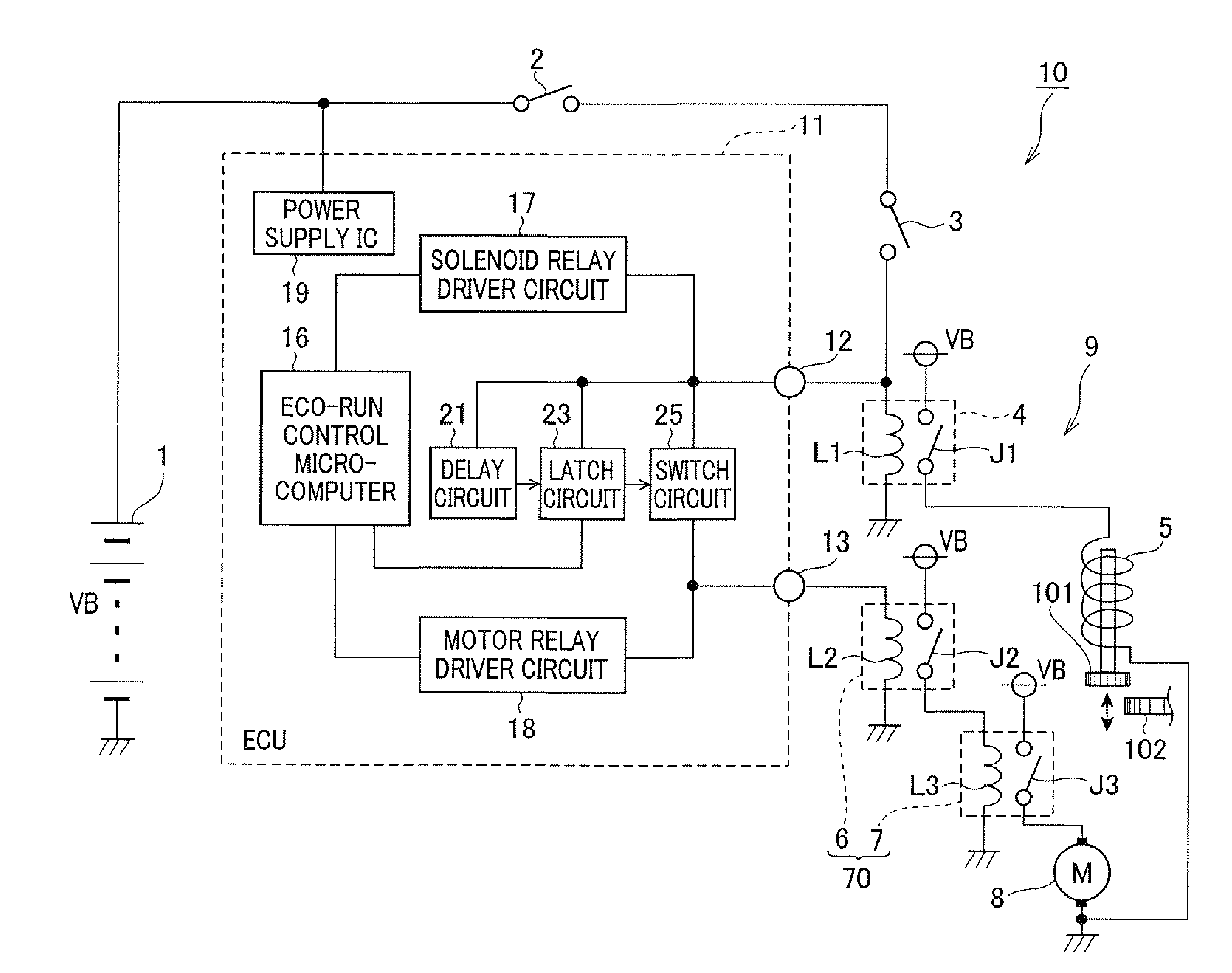
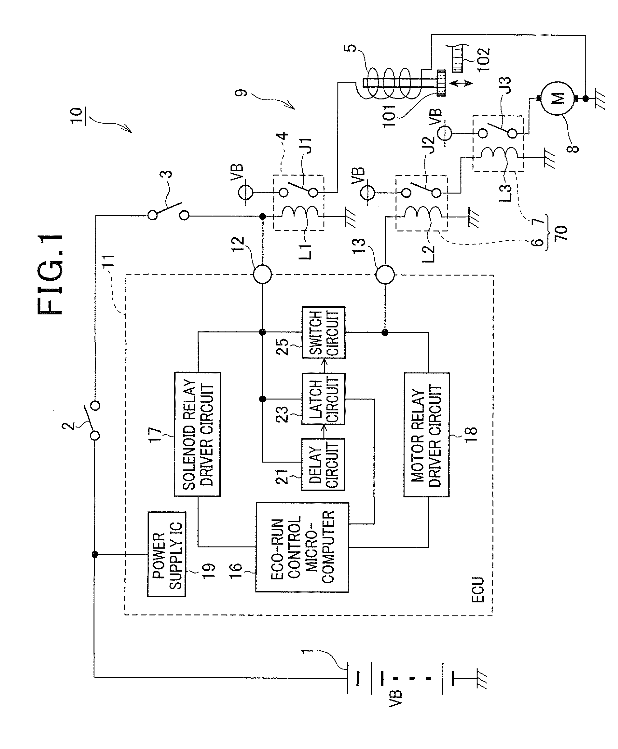
[0031]FIG. 1 is a block diagram schematically showing the structure of an engine starting apparatus 10 according to a first embodiment of the invention. The engine starting apparatus 10, which is mounted on a vehicle to control starting of a vehicle engine, includes a battery 1, a starter 9 which operates on electric power supplied from the battery 1, and an ECU 11 for controlling the operation of the starter 9.

[0032]The battery 1 is mounted on the vehicle for supplying electric power to various components in the vehicle including the starter 9 and the ECU 11. In this embodiment, the rated terminal voltage of the battery 1 (referred to as the battery voltage VB hereinafter) is 12 V.

[0033]The starter 9 includes a pinion 101, a pinion-engagement controlling solenoid 5, a solenoid relay 4, a starter motor 8, a first motor relay 7 and a second motor relay 6. The pinion 101 is configured to engage with a ring gear 102 formed in the outer periphery of a flywheel disposed at an end of a cr...

second embodiment

[0132]Next, an engine starting apparatus 30 according to a second embodiment of the invention is described with reference to FIG. 5. In FIG. 5, the reference numerals and characters identical to those in FIG. 1 represent the same elements.

[0133]As shown in FIG. 5, the engine starting apparatus 30 includes a push switch 34 which is operated by the user of the vehicle to start the engine. This push switch 34 is connected to a push switch signal input terminal 32 of an ECU 31.

[0134]The ECU 31 includes a start control microcomputer 35, a starting circuit 36, and a start signal output terminal 33. The start control microcomputer 35 controls the starting circuit 36 depending on the operation state of the push switch 34 to output a start signal to the solenoid relay 4 through the start signal output terminal 33.

[0135]The engine starting apparatus 30, which is able to implement the so-called push start system, is configured such that when the push switch 34 is pushed on while the user press...

third embodiment

[0140]Next, an engine starting apparatus 40 according to a third embodiment of the invention is described with reference to FIG. 6. in FIG. 6, the reference numerals and characters identical to those in FIG. 1 represent the same elements.

[0141]As shown in FIG. 6, in this embodiment, a diode D2 is provided between the neutral switch 3 and the solenoid relay 4. In more detail, the diode D2 is connected to the neutral switch 3 and a battery voltage input terminal 42 of an ECU 41 at its anode, and connected to the solenoid relay 4 and the solenoid relay driving terminal 12 of the ECU 41 at its cathode.

[0142]The ECU 41 has a structure similar to that of the ECU 11 of the first embodiment. However, the ECU 41 differs from the ECU 11 in the following points. In the ECU 41 of this embodiment, the solenoid relay driving terminal 12 is not connected to any of the switch circuit 25, delay circuit 21 and latch circuit 23. Accordingly, the drive signal outputted from the solenoid relay driver ci...


PUM


Abstract

The engine starting apparatus operates on battery voltage when the battery voltage is higher than a predetermined voltage to control starting of an engine of a vehicle. The engine starting apparatus includes a relay control section configured to output a drive signal individually to first and second relays of a starter of the vehicle engine to drive the first and second relays when predetermined engine start conditions are satisfied, the starter being configured to operate when the first and second relays are driven, and an inter-relay switch configured to make electrical connection between the first and second relays when the first relay is applied with the battery voltage, the second relay being applied with the battery voltage when the electrical connection is made. The first relay is configured to be applied with the battery voltage when a manual start switch is operated.

Description

CROSS-REFERENCE TO RELATED APPLICATION[0001]This application is related to Japanese Patent Application No. 2008-264516 filed on Oct. 10, 2008, the contents of which are hereby incorporated by reference.BACKGROUND OF THE INVENTION[0002]1. Field of the Invention[0003]The present invention relates to an apparatus mounted on a vehicle for starting an engine mounted on the vehicle.[0004]2. Description of Related Art[0005]In recent years, there has been developed and put to practical use a so-called idle stop system which automatically stops an engine of a vehicle when the engine is not needed to run, for example, while the vehicle stops at a red light, and automatically restarts the engine when the engine becomes needed to run, in view of reduction of fuel consumption and discharged exhaust gas.[0006]The vehicle provided with such an idle stop system is strongly required that the starter thereof is sufficiently quiet and durable, because its engine stops and restarts at frequent interval...

Claims


Application Information

Patent Timeline
Patent Type & Authority Applications(United States)
IPC IPC(8): B60L1/00
CPCF02N11/0814F02N11/0862Y02T10/48F02N11/103F02N2250/02F02N11/087Y02T10/40
Inventor ITOU, AKITO
Owner DENSO CORP
Why Eureka
Try Eureka