Optical scanning device and image forming apparatus

a scanning device and image forming technology, applied in the field of digital optical writing system, can solve the problems of uneven temperature distribution of the optical housing, affecting the image quality of the image, and the displacement of the beam spot on the photosensitive member,

Inactive Publication Date: 2010-04-15
RICOH KK
View PDF19 Cites 76 Cited by
  • Summary
  • Abstract
  • Description
  • Claims
  • Application Information

AI Technical Summary

Benefits of technology

[0023]Furthermore, according to another aspect of the present invention, there is provided an image forming apparatus that forms an image on a recording medium by forming a latent image on a photosensitive medium by an optical scanning using an optical scanning device and developing the latent image with toner. The optical scanning device includes an optical housing in which a polygon mirror that is rotated by a driving force from a motor is accommodated, an air inlet that includes a filter, an airflow guiding member that is arranged at a position opposite to a surface of the polygon mirror on the air inlet side, for preventing an air circulation around the polygon mirror, and an air inducing path that includes a first flowing path including a first end that is linked to the air inlet and a second end that is arranged close to a mirror surface of the polygon mirror and a second flowing path that is formed with a surface of the airflow guiding member on an opposite side of the air inlet and a top surface of the polygon mirror.

Problems solved by technology

This causes an optical housing to have uneven temperature distribution (temperature difference).
The temperature rise and the uneven temperature distribution in the optical housing can cause an optical component, such as a mirror, to be deformed or move a position where the optical component is fixed, thereby causing beam spot displacement on a photosensitive member and degradation in image quality to occur.
The larger the temperature rise, the larger the beam spot displacement and the degree of the degradation in image quality.
However, this conventional structure is disadvantageous in requiring additional space for the duct around the optical housing, which inhibits compact construction of an image forming apparatus.
The conventional structure is also disadvantageous in being less environmentally friendly because driving the fan increases power consumption.
The conventional structure is also disadvantageous in that because cooling is provided from the outside of the optical housing that incorporates heat sources, a large motor fan is required to obtain sufficient cooling effect.
The conducted heat causes the optical housing to be deformed, resulting in beam spot displacement on the photosensitive member and degradation image quality.
However, with the conventional structures, because airflow circulates over the polygon mirror as depicted in FIG. 10 or FIG. 11, an amount of intake air is insufficient, and the pressure does not build up in the optical housing sufficiently.
Accordingly, air exhaustion and cooling effect resulting therefrom have been insufficient.
The conventional structures have also been disadvantageous in that fine dusts flown into the optical housing through a gap between a housing cover and the optical housing and gaseous contaminants that have passed through the filter are conveyed by the circulation flow over the polygon mirror and stick to the polygon mirror, thereby causing mirror surfaces of the polygon mirror to be hazed.
This temperature deviation causes optical elements and components that support the optical elements to thermally expand nonuniformly, which results in chromatic misregistration.
However, even when such a suction air duct is provided, wind noise produced by the rotating polygon mirror comes out of the optical housing because sufficient attenuation of the wind noise cannot be achieved only by the suction air duct.
However, because a load placed on a polygon-mirror drive motor is increased by a load required to drive the fan, an amount of electric current supplied to the drive motor increases, which increases power consumption and hence an amount of heat produced by the drive motor.
In other words, when a fan is additionally provided in an optical scanning device, power consumption by the optical scanning device increases as compared with an optical scanning device without a fan, disadvantageously making the optical scanning device with the fan less environmentally friendly.
Addition of an air inlet to the optical scanning device brings about an increase in noise power level.

Method used


Image

  • Optical scanning device and image forming apparatus
  • Optical scanning device and image forming apparatus
  • Optical scanning device and image forming apparatus

Examples


first embodiment

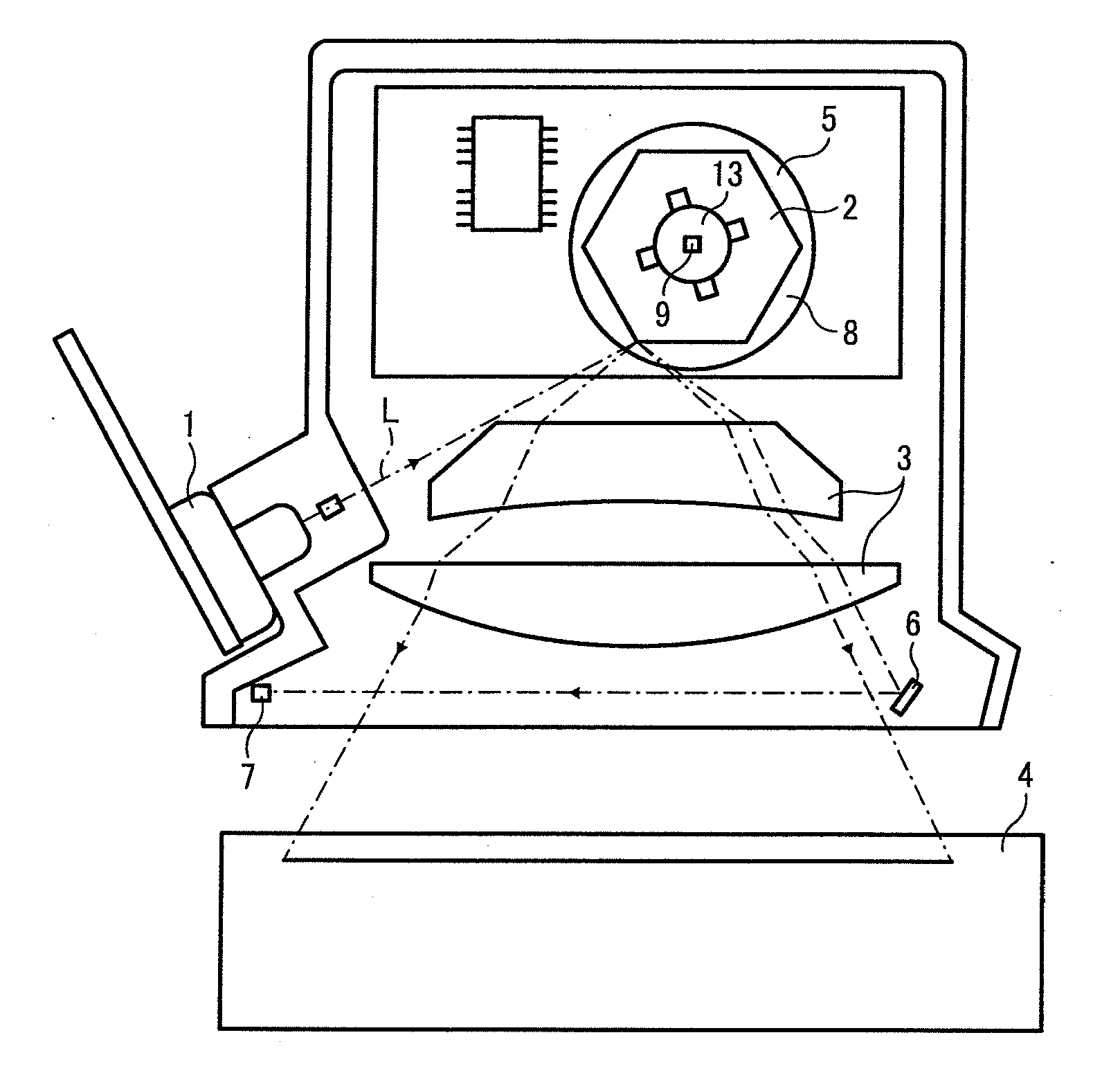
[0052]FIG. 1 is a schematic diagram of an optical scanning device according to the present invention.

[0053]The optical scanning device includes a laser emitter 1, a polygon mirror 2, a set of condensing lenses 3, a photosensitive drum 4, a motor 5, a reflector 6, a detector 7, and an optical housing 14. The laser emitter 1, which is a light source device, emits a laser beam L.

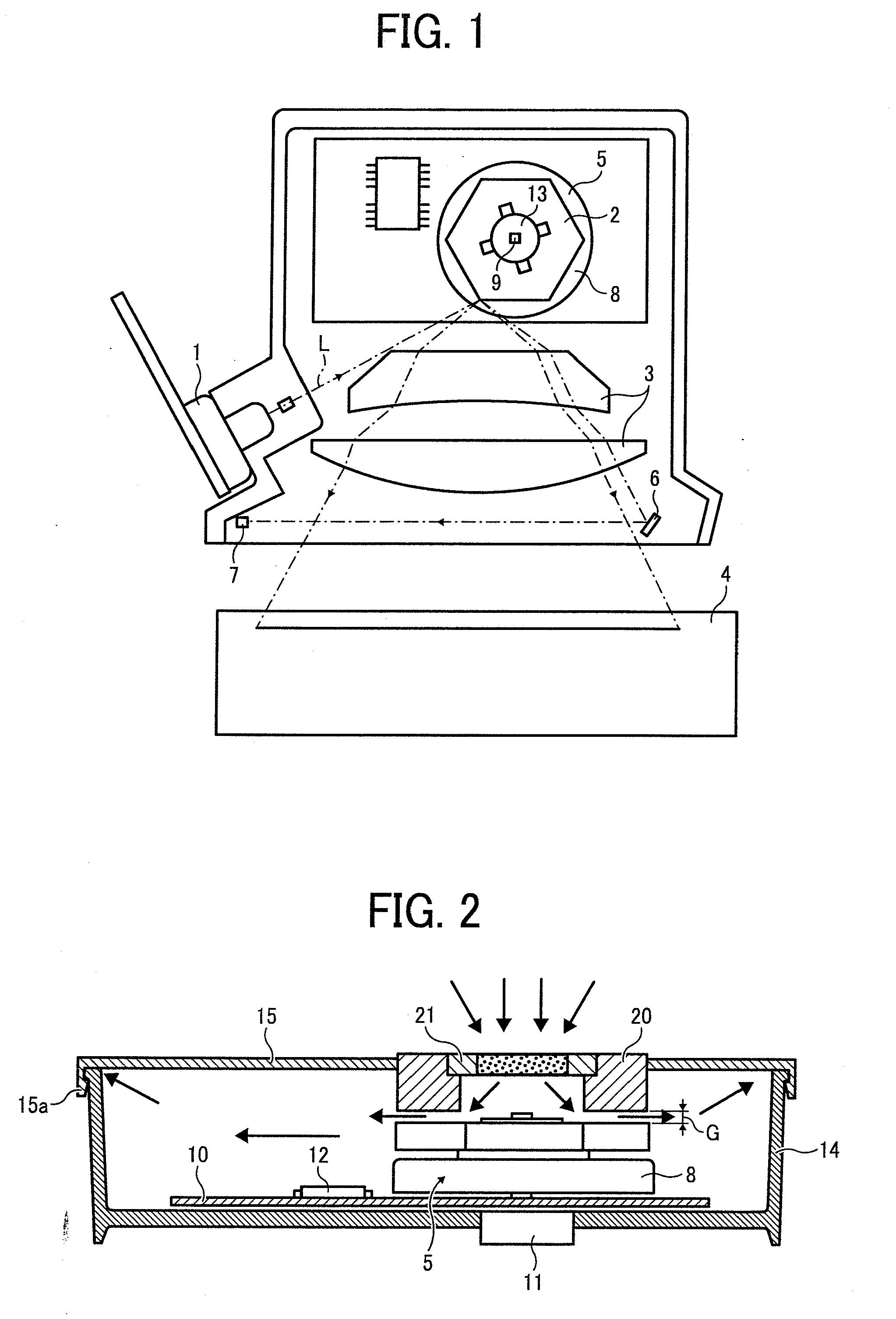
[0054]FIG. 2 is a schematic cross-sectional view of the optical housing 14.

[0055]The laser beam L emitted from the laser emitter 1 is reflected from the polygon mirror 2 and travels through the condensing lenses 3 to be focused on the photosensitive drum 4. At the same time, the polygon mirror 2 is rotated by the motor 5 so that a portion of the laser beam L is reflected from the reflector 6 to enter the detector 7. The detector 7 outputs a detection signal used to determine write timing for the laser beam L on a scan-line-by-scan-line basis.

[0056]The motor 5 includes a rotor 8, a rotation shaft 9, a motor circ...

second embodiment

[0071]FIGS. 5A and 5B are schematic cross-sectional views of an optical scanning device according to the present invention. FIG. 5A is a schematic view for illustrating a conical flowing path in an optical housing of the optical scanning device. FIG. 5B is a schematic view of a modification of the conical flowing path.

[0072]FIGS. 6A and 6B are schematic perspective views for illustrating a relationship in view of size between an airflow guiding member 30 and polygon mirrors 140a depicted in FIG. 5A.

[0073]The polygon mirrors 140a are housed in a core casing 700. The core casing is housed in an outer casing 710 and attached thereto. A polygon scanner 140 includes the polygon mirrors 140a arranged in two layers. A lid 711 is fixed to the outer casing 710 to prevent dusts or the like from entering inside the optical housing 14 from the outside. A reflector, an elongated lens, and the like are omitted from FIGS. 5A to 6B.

[0074]As depicted in FIG. 5A, the airflow guiding member 30 is arra...

third embodiment

[0091]An optical scanning device according to the present invention applied to the image forming apparatus will be described below.

[0092]Although the image forming apparatus differs from conventional image forming apparatuses in the structure of the optical scanning device, major components of the image forming apparatus are basically the same with those of the conventional image forming apparatuses. Hence, descriptions of the image forming apparatus are omitted.

[0093]The optical scanning device according to the third embodiment includes polygon mirrors arranged in two layers. As a matter of course, the present invention is applicable to an image forming apparatus that includes an optical scanning device that includes a single-layer polygon mirror as does the optical scanning device according to the first embodiment.

[0094]The present invention is applicable to most optical scanning devices and image forming apparatuses that include a polygon mirror. For example, the present inventio...


PUM


Abstract

An optical scanning device includes an optical housing in which a polygon mirror that is rotated by a motor is accommodated and an air inlet that includes a filter. An airflow guiding member is arranged at a position opposite to a surface of the polygon mirror on the air inlet side. An air inducing path is provided, which includes a first flowing path and a second flowing path. The first flowing path includes a first end linked to the air inlet and a second end arranged close to a mirror surface of the polygon mirror. The second flowing path is formed with a surface of the airflow guiding member on an opposite side of the air inlet and a top surface of the polygon mirror.

Description

CROSS-REFERENCE TO RELATED APPLICATIONS[0001]The present application claims priority to and incorporates by reference the entire contents of Japanese Patent Application No. 2008-226358 filed in Japan on Sep. 3, 2008, Japanese Patent Application No. 2008-264495 filed in Japan on Oct. 10, 2008 and Japanese Patent Application No. 2009-024060 filed in Japan on Feb. 4, 2009.BACKGROUND OF THE INVENTION[0002]1. Field of the Invention[0003]The present invention relates to a digital optical writing system, and more particularly, to an optical scanning device for use in a digital output device, such as a printer and a facsimile machine, and image forming apparatus that uses the optical scanning device.[0004]2. Description of the Related Art[0005]In an optical scanning device for use in an image forming apparatus, temperature generally increases at and around an optical deflector under application of heat produced by a rotating polygon mirror. This causes an optical housing to have uneven temp...

Claims


Application Information

Patent Timeline
Patent Type & Authority Applications(United States)
IPC IPC(8): G02B26/10B41J27/00B41J2/435
CPCB41J2/471G02B27/0006G02B26/12
Inventor ITAMI, YUKIOOHSUGI, TOMOYAAOKI, MAGANENAKAJIMA, TOMOHIROHAYASHI, YOSHINORIMIYATAKE, NAOKIMASUDA, KENSUKEWATANABE, NAOTOTSUCHIYA, SATOSHI
Owner RICOH KK
Why Eureka
Try Eureka