Pressure balanced valve assembly and aircraft buffer cooler system employing the same

a valve assembly and valve body technology, applied in the field of aircraft systems, can solve the problems of air pressure within the selected gte compressor stage to become undesirably high or undesirably low, air pressure within the higher compressor stage and pressure within the bearing assembly to become undesirably high or low

Inactive Publication Date: 2010-04-15
HONEYWELL INT INC
View PDF2 Cites 66 Cited by
  • Summary
  • Abstract
  • Description
  • Claims
  • Application Information

AI Technical Summary

Problems solved by technology

Depending upon the particular compressor stage from which the buffer cooler system draws pressurized air, the air pressure within the selected GTE compressor stage may become undesirably high or undesirably low during GTE operation for the purposes of pressurizing the bearing assembly's air cavity.
For example, if the aircraft buffer cooler system is configured to draw pressurized air from a higher compressor stage (e.g., the 6th stage of an aircraft compressor), the air pressure within the selected compressor stage may be ideal for pressurizing the bearing assembly during low engine speed conditions, such as engine start and flight idle; however, the pressure within the higher

Method used


Image

  • Pressure balanced valve assembly and aircraft buffer cooler system employing the same
  • Pressure balanced valve assembly and aircraft buffer cooler system employing the same
  • Pressure balanced valve assembly and aircraft buffer cooler system employing the same

Examples


Embodiment Construction

[0011]The following Detailed Description is merely exemplary in nature and is not intended to limit the invention or the application and uses of the invention. Furthermore, there is no intention to be bound by any theory presented in the preceding Background or the following Detailed Description.

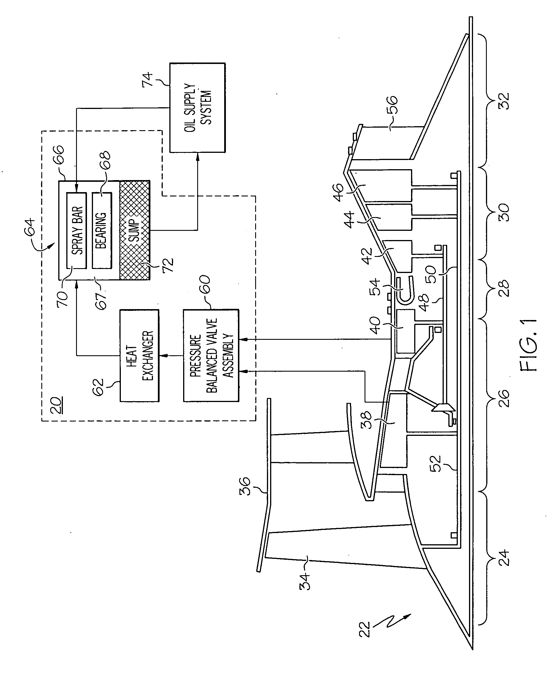
[0012]FIG. 1 is a functional schematic of an aircraft buffer cooler system 20 in accordance with an exemplary embodiment of the present invention. By way of contextual example only, aircraft buffer cooler system 20 is illustrated in conjunction with a gas turbine engine (GTE) 22 of the type commonly deployed on an aircraft. In this particular example, GTE 22 assumes the form of a three spool turbofan engine including an intake section 24, a compressor section 26, a combustion section 28, a turbine section 30, and an exhaust section 32. Intake section 24 includes a fan 34 mounted in a fan case 36. Compressor section 26 includes one or more compressors (e.g., an intermediate pressure (IP) comp...


PUM


Abstract

A pressure balanced valve assembly is provided. In one embodiment, the pressure balanced valve assembly includes a housing assembly having first and second seats. A flow passage formed through the housing assembly includes a first inlet, a second inlet, and an outlet. A piston is slidably mounted in the housing assembly for movement between: (i) a first position wherein the piston contacts the second seat to restrict fluid flow from the second inlet to the outlet, and (ii) a second position wherein the piston contacts the first seat to restrict fluid flow from the first inlet to the outlet. First and second dynamic seals are mounted in the housing assembly. The first and second dynamic seals sealingly engage first and second portions of the piston over areas substantially equivalent to the sealing areas of the second and first seats, respectively.

Description

TECHNICAL FIELD[0001]The present invention relates generally to aircraft systems and, more particularly, to a pressure balanced valve assembly suitable for deployment within an aircraft buffer cooler system.BACKGROUND[0002]A gas turbine engine (GTE) is commonly equipped with a lubrication system that continually circulates a lubricant, typically oil, through the GTE's bearing assemblies. The lubrication system may include, for example, an oil tank; a spray bar mounted within the bearing housing above the bearing or bearings contained therein; and a supply pump fluidly coupled between the oil tank and the spray bar. When energized, the supply pump draws oil from the oil tank and supplies the oil to the spray bar, which then directs the oil over the bearing assembly's bearings. After flowing through the bearings, the oil collects within a sump provided at the bottom of the bearing housing. The oil is then returned to the oil tank, and the process is repeated.[0003]The GTE bearing asse...

Claims


Application Information

Patent Timeline
IPC IPC(8): F16C37/00F16K11/065
CPCF01D25/125F01D25/183F16C33/6692F16C37/00F16C2360/23F16K31/363Y02T50/675F05D2270/3015F16K11/044F16C33/667F16C37/007Y10T137/86815Y02T50/60
Inventor FRANCONI, ROBERT B.
Owner HONEYWELL INT INC
Why Eureka
Try Eureka