Method and system for fiber-optic monitoring of spatially distributed components

Active Publication Date: 2010-04-15
PRYSMIAN SPA
View PDF4 Cites 7 Cited by
  • Summary
  • Abstract
  • Description
  • Claims
  • Application Information

AI Technical Summary

Benefits of technology

[0048]Preferably, a fraction of the optical radiation that is spilled by each optic

Problems solved by technology

Indeed, the presence of local feeding devices for the monitoring device or component could give rise to the same problems and troubles set for the above in connection to the ancillary elements.

Method used


Image

  • Method and system for fiber-optic monitoring of spatially distributed components
  • Method and system for fiber-optic monitoring of spatially distributed components
  • Method and system for fiber-optic monitoring of spatially distributed components

Examples


Embodiment Construction

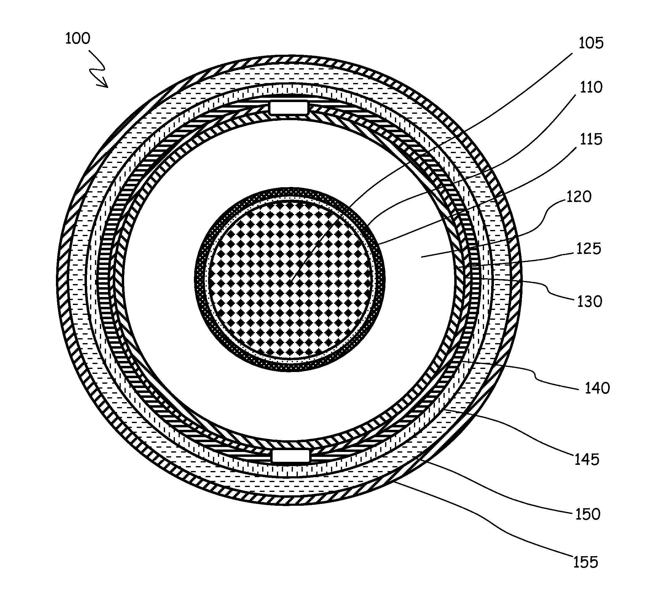
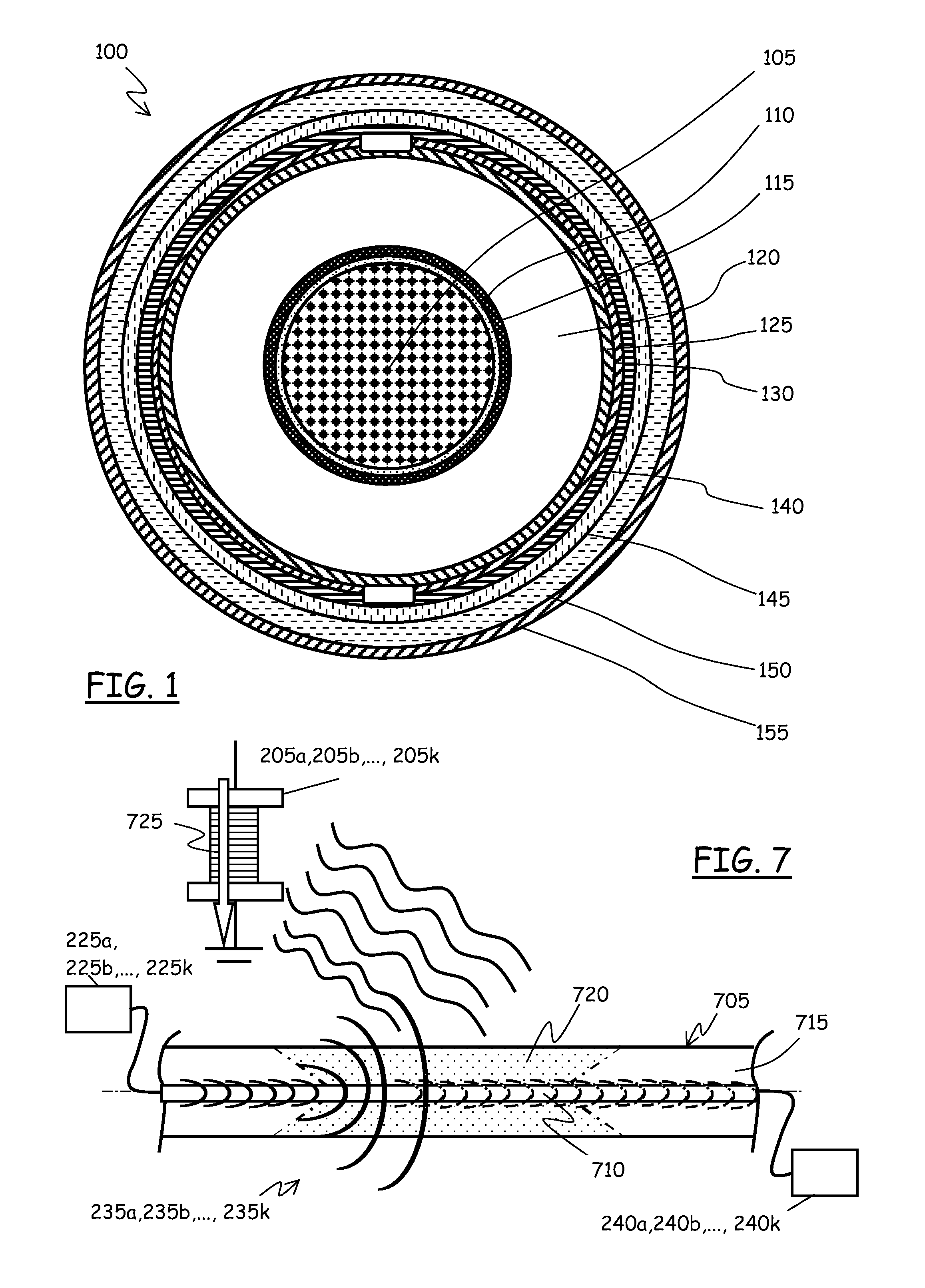
[0068]FIG. 1 shows, in cross section, a cable 100 for HV electric power distribution networks; particularly a single-core cable. The cable 100 comprises, starting from the center thereof and moving radially outwards, a central conductor 105, a binder 110, made of a semi-conductive tape, a conductor screen 115, made of a semi-conductive polymer, an insulation layer 120 made, for example, of cross-linked polyethylene (XLPE), an insulation screen 125, also made of a semi-conductive polymer, a semi-conductive water barrier 130, made for example of a semi-conductive hygroscopic tape, a metallic sheath 140, made of a metal sheet, a jacket 145 of high-density polyethylene (HDPE), and finally a protective coating 150, typically semi-conductive. The cable 100 can be used both in aerial applications or underground.

[0069]The metallic sheath 140 has primarily the function of making the electromagnetic field uniform around the conductor 105.

[0070]Phenomena like lightning, switch-on maneuvers of ...


PUM


Abstract

A system for monitoring ancillary elements of an electric power distribution network, includes an optical fiber path associated with the ancillary elements to be monitored, respective optical branches branching from the optical fiber path, wherein each optical branch includes at least one passive optical attenuator operatively coupled to, and having an attenuation adapted to change in response to a change in operating conditions of the respective ancillary element, and an optical reflector; an optical radiation source adapted to inject optical radiation into the optical fiber path; and an optical receiver adapted to detect back-reflected optical radiation reflected by the optical reflector; the monitoring system being further adapted to recognize a position of at least one of the ancillary elements based on a characteristic of the back-reflected optical radiation.

Description

BACKGROUND OF THE INVENTION[0001]1. Field of the Invention[0002]The present invention generally relates to methods and systems for monitoring electric power distribution system components distributed in a plurality of locations. In particular, the invention concerns the monitoring, in real time and by exploiting optical fibers, of the state and condition of “ancillary” elements, for example protection elements used in electric power distribution systems for ensuring the system security.[0003]2. Description of Related Art[0004]Distribution systems of electric power comprise distribution networks, for example high voltage (HV) distribution networks.[0005]The term “high voltage” is related to voltages higher than 35 kV, reaching also one or more hundreds of kilovolts.[0006]The distribution networks make use of cables that may, for example, be aerial (overhead) or underground, for example positioned in tunnels.[0007]In addition to cables, distribution networks can comprise a number of d...

Claims


Application Information

Patent Timeline
IPC IPC(8): H04B10/00
CPCG01D5/35358H02J13/0065H04M11/04H02J13/00019H02J13/00017Y04S40/124Y02E60/00
Inventor SARCHI, DAVIDEGASPARI, ROBERTOCOLETTA, GIACOMOVILLANI, GIOVANNI
Owner PRYSMIAN SPA
Why Eureka
Try Eureka