Optimization of air cooled chiller system operation

a chiller and air technology, applied in the direction of adaptive control, domestic cooling equipment, instruments, etc., can solve the problem that the chiller system operates at less than the optimal energy efficiency rating, and achieve the effect of reducing the error function, increasing the speed of the condenser fan, and minimizing the error function

Active Publication Date: 2010-04-15
CARRIER CORP
View PDF15 Cites 36 Cited by
  • Summary
  • Abstract
  • Description
  • Claims
  • Application Information

AI Technical Summary

Benefits of technology

[0010]The step of comparing the sensed instantaneous value of the control parameter to the calculated control parameter set point may comprise the step of comparing the SDTi to the SDTSP. In an embodiment, if SDTSP−ΔSDT≦SDTi≦STDSP+ΔSDT, where ΔSDT is the preselected tolerance, then SDTi is within the preselected tolerance of SDTSP and the condenser fan speed is maintained at its current speed. If SDTi is less than SDTSP−ΔSDT, where ΔSDT is the preselected tolerance, the condenser fan speed is increased. If SDTi is greater than SDTSP+ΔSDT, where ΔSDT is the preselected tolerance, the condenser fan speed is decreased.
[0011]In an embodiment, the step of adjusting an operating speed of the condenser fan in response to the comparison of the sensed instantaneous value of the control parameter to the calculated control parameter set point comprises the steps of: calculating an error function, ε, by the formula: ε=SDTi−SDTSP; processing the calculated error function via a PID formulation to generate a fan speed command signal; and adjusting the speed of the condenser fan in response to the fan speed command signal to minimize the error function.
[0012]In an embodiment, the step of adjusting an operating speed of the condenser fan in response to the comparison of the sensed instantaneous value of the control parameter to the calculated control parameter set point comprises the steps of: determining a deviation of the sensed saturated discharge temperature from the calculated desired saturated discharge temperature set point; processing the calculated deviation via a fuzzy logic technique to generate a fan speed command signal; and adjusting the speed of the condenser fan in response to the fan speed command signal to minimize the error function

Problems solved by technology

Consequently, the chiller system is operated at less than its optimal energy efficiency rating over a wide portion of its operational envelope.

Method used


Image

  • Optimization of air cooled chiller system operation
  • Optimization of air cooled chiller system operation
  • Optimization of air cooled chiller system operation

Examples


Embodiment Construction

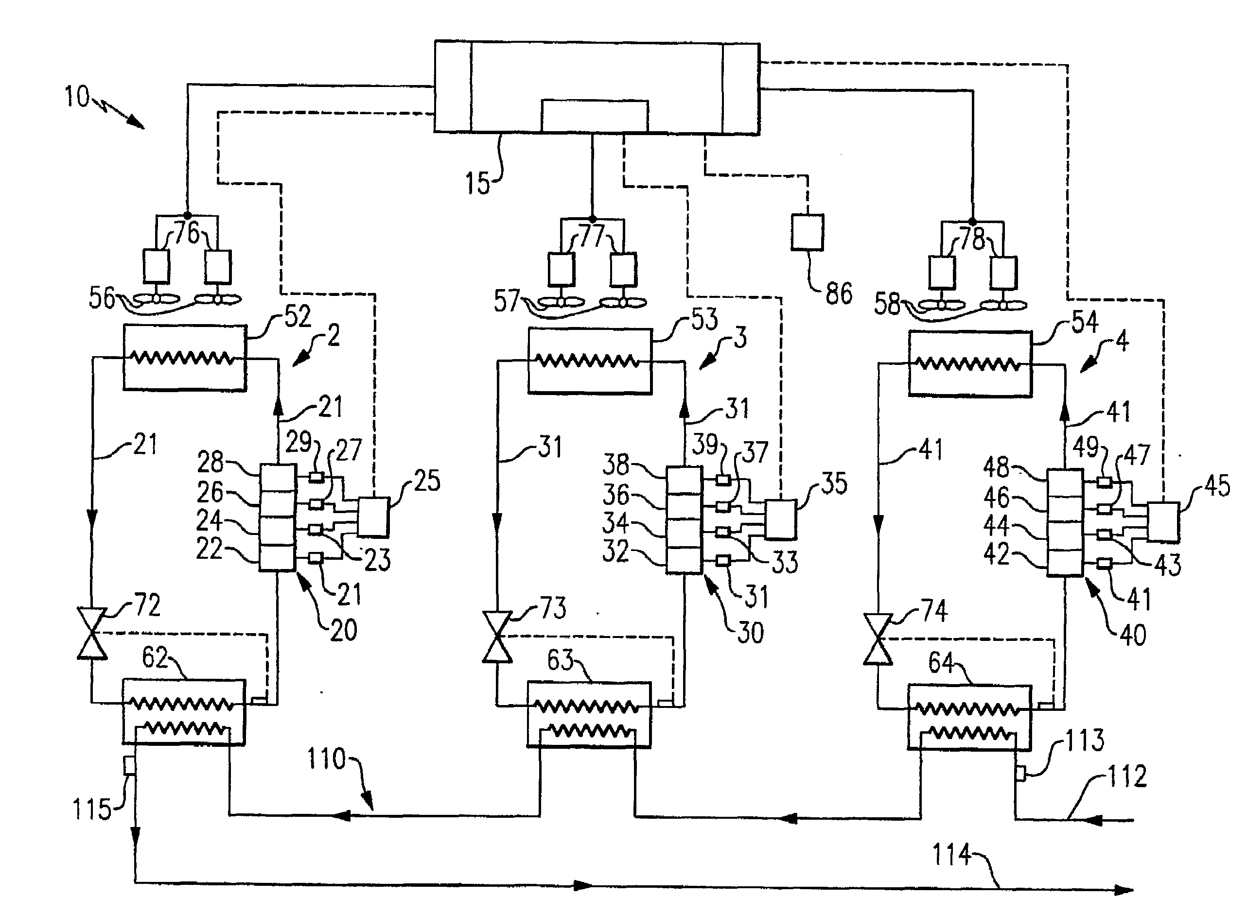
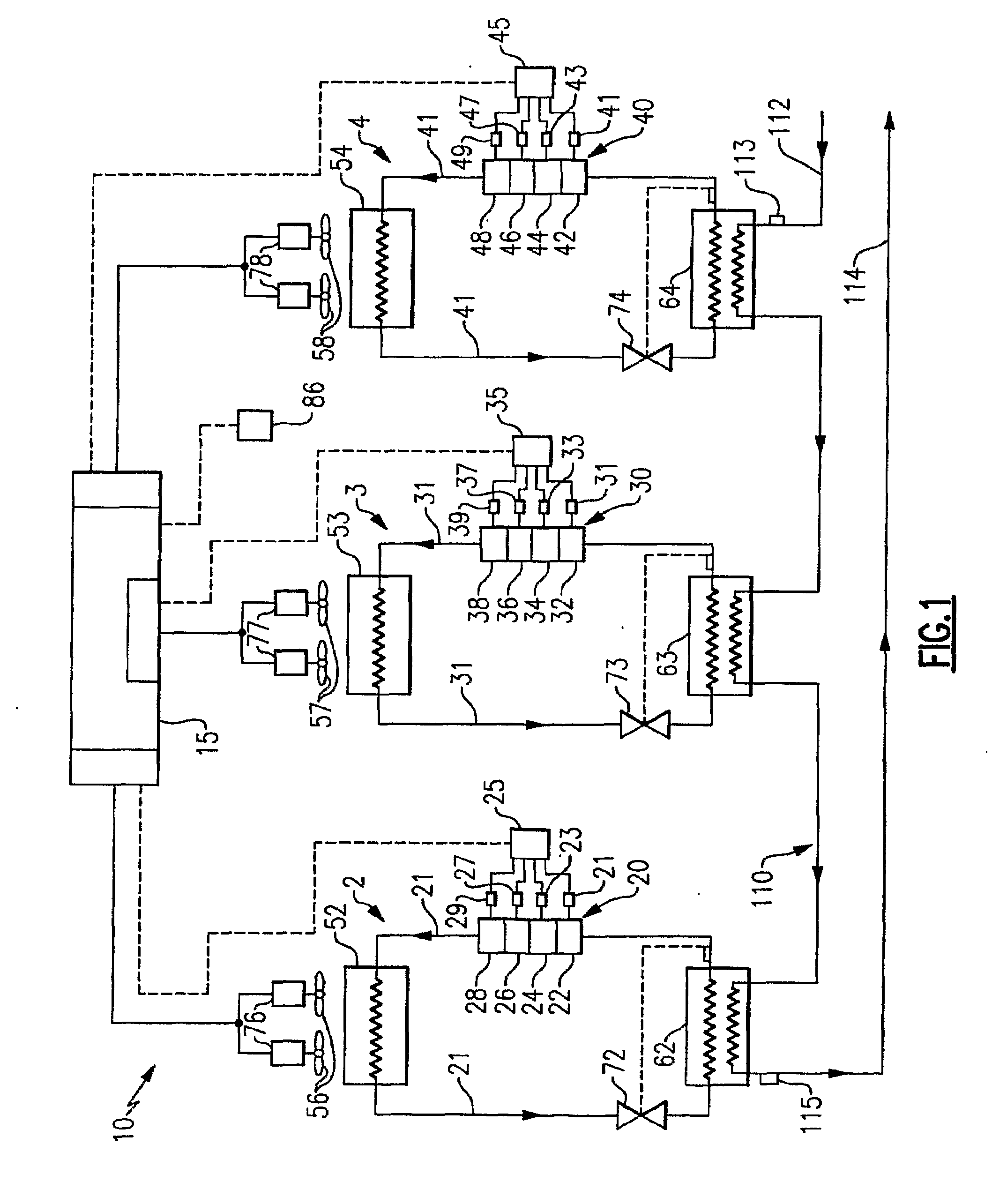
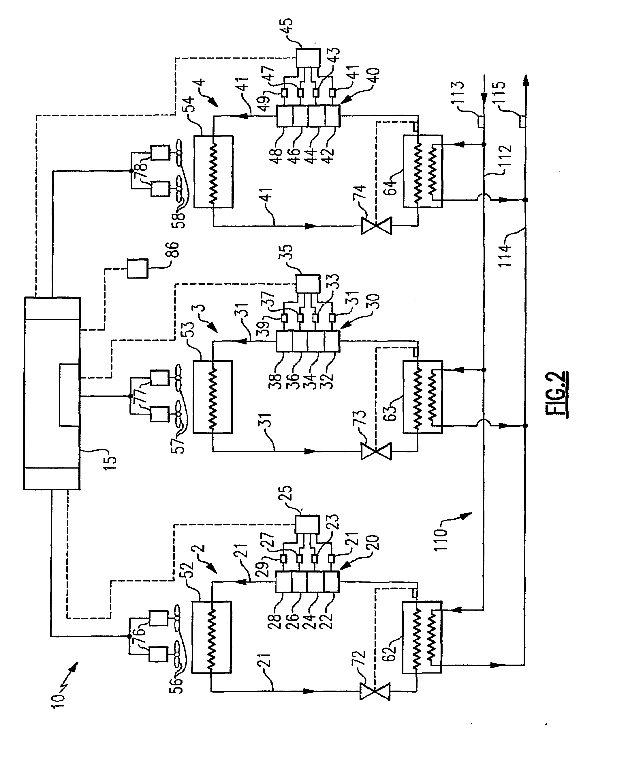
[0021]Referring now to FIGS. 1 and 2, in particular, there are depicted exemplary embodiments of a chiller system 10 including three independent air-cooled refrigeration units 2, 3 and 4 disposed in operative association with a chilled fluid circuit 110. In further discussion of the invention with reference to the chiller system 10, the chilled fluid will be referred to herein as cooling water, although it is be understood that the method of the invention may be applied equally well to chiller systems using cooling fluids other than water. Each of the refrigeration units 2, 3, 4 includes a compressor rack, a condenser, an evaporator and an expansion device disposed conventionally in refrigerant circuit 21, 31, 41, respectively, in a conventional refrigerant vapor compression cycle. Refrigerant circuit 21 of chiller unit 2 includes compressor rack 20, condenser 52, evaporator 62 and an expansion device 72 disposed downstream with respect to refrigerant flow of the condenser 52 and up...


PUM


Abstract

A method is provided for operating a refrigerant vapor compression system, for example an air-cooled chiller or air-cooled condensing unit, at optimal energy efficiency rating. The method includes the steps of: determining the instantaneous values of a plurality of selected operating parameters of the system's refrigeration unit, calculating a desired control parameter set point indicative of an optimal energy efficiency rating for the refrigeration unit as a function of the selected operating parameters, sensing the instantaneous value of the control parameter, comparing the sensed instantaneous value of the control parameter to the calculated control parameter set point, and adjusting the operating speed of the condenser fans associated with the air-cooled condenser of the refrigeration unit in response to that comparison.

Description

FIELD OF THE INVENTION[0001]This invention relates in general to optimizing the energy efficiency rating over a range of operating conditions for a refrigerant vapor compression system, such as for example a chiller system, a condensing unit, or the like, having one or more air-cooled condensers. More particularly, the invention relates to controlling each individual refrigeration unit within the chiller system to operate at its optimum energy efficiency by varying the control set-point of a system control parameter in response to operating conditions.BACKGROUND OF THE INVENTION[0002]Air-cooled chiller systems are well known in the art and commonly used in cooling the air in commercial buildings, schools, hospitals, restaurants and the like. A conventional air-cooled chiller system includes one or more refrigeration units having respective closed loop refrigerant circuits in operative association with a cooling fluid circuit. Each refrigeration unit includes a compressor rack having...

Claims


Application Information

Patent Timeline
Patent Type & Authority Applications(United States)
IPC IPC(8): G05B13/00F25B41/00F25D17/06
CPCF25B1/10F25B49/027F25B2600/0251Y02B30/743F25B2700/21152F25B2700/2116F25B2700/21173F25B2600/111Y02B30/70
Inventor BALLET, JOSEPHGRABON, MICHEL KAROL
Owner CARRIER CORP
Why Eureka
Try Eureka