
Method of manufacturing a cutting member of a shaver

a cutting member and shaver technology, applied in the direction of cutlery, liquid handling, transportation and packaging, etc., can solve the problems of increasing the dimensions of the carrier, reducing the mechanical strength of the carrier, and not always being able to meet the requirements of the customer, so as to reduce prevent the location of the cutting edge. , the effect of reducing the strength of the carrier

Active Publication Date: 2010-04-22
KONINKLIJKE PHILIPS ELECTRONICS NV
View PDF5 Cites 14 Cited by
  • Summary
  • Abstract
  • Description
  • Claims
  • Application Information

AI Technical Summary

Benefits of technology

[0005]In order to achieve this object, a method of manufacturing a cutting member according to the invention is characterized in that the steps of cutting free and bending the cutting element are performed simultaneously using a tool having a combined punching and bending effect. By using a tool having a combined punching and bending effect, the cutting element is teared free and simultaneously bent out of the carrier. Accordingly the action of cutting free is obtained by a tearing process, which does not lead to a free space between the cutting element and the carrier. As a result, the strength of the carrier is not decreased by a free space between the cutting element and the carrier, so that the dimensions of the carrier need not be increased to remain a required strength of the carrier. An additional advantage of the method according to the invention is that, close to the residual connection between the base of the cutting element and the carrier, the side walls of the cutting element remain in contact with the carrier. As a result the carrier provides additional mechanical support to the cutting element via friction forces between the carrier and the portions of the side walls that are in contact with the carrier. This increases the stiffness and stability of the cutting elements.
[0007]A particular embodiment of a method according to the invention is characterized in that the tool has a punching surface that, during the simultaneous steps of cutting free and bending the cutting element, has an angle of inclination relative to the carrier substantially corresponding with a desired bending angle of the cutting element relative to the carrier. In this particular embodiment the simultaneous steps of cutting free and bending take place in successive positions starting near an end portion of the cutting element and ending close to the base of the cutting element. This limits the punching force necessary to tear free and bend the cutting element.
[0010]A particular embodiment of a method according to the invention is characterized in that before the simultaneous steps of cutting free and bending the cutting element a free space is cut between the carrier and an end portion of the cutting element carrying a cutting edge. In this particular embodiment, by first cutting free said end portion using a suitable cutting die to cut a free space between said end portion and the carrier, only the remaining portion of the cutting element between said end portion and the base is teared free from the carrier. As a result, burrs at the location of the cutting edge are prevented, while the reduction of the strength of the carrier by the free space is limited to the area around the end portion of the cutting element.

Problems solved by technology

A disadvantage of the known method is that the free space cut around the cutting element during the step of cutting free decreases the mechanical strength of the carrier.
Such an increase of the dimensions of the carrier is not always allowable, in particular in the case of shavers or cutting units thereof that have only a limited available space to accommodate the cutting member.

Method used


Image

  • Method of manufacturing a cutting member of a shaver
  • Method of manufacturing a cutting member of a shaver
  • Method of manufacturing a cutting member of a shaver

Examples


Embodiment Construction

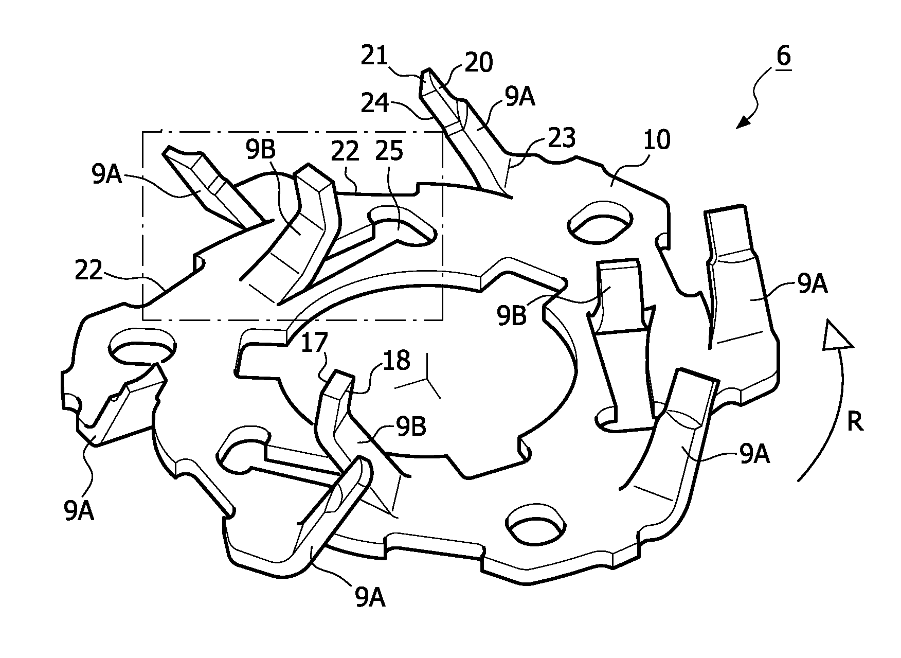
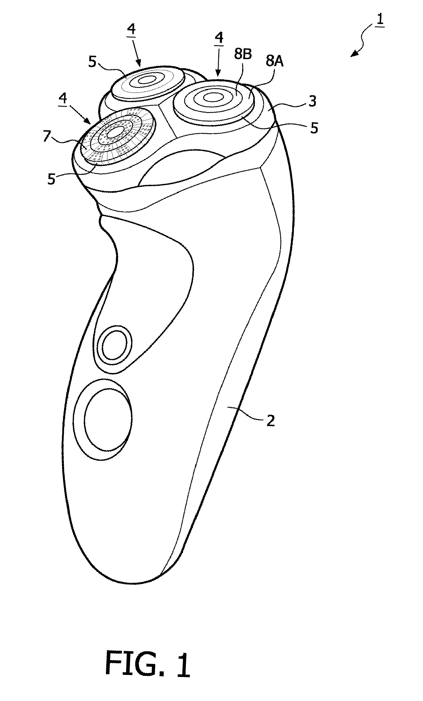
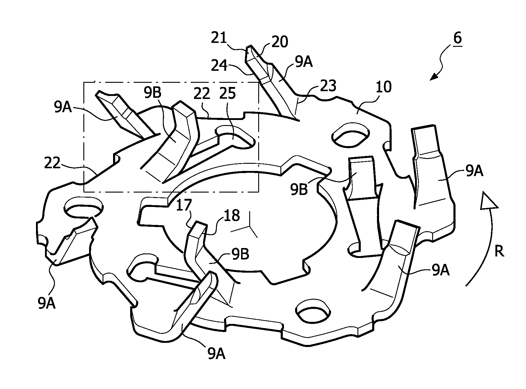
[0018]FIG. 1 shows an example of a shaver 1 according to the invention. The shaver 1 is an electric rotary shaver and comprises a basic housing 2 on which a shaving unit 3 according to the invention is mounted. The shaving unit 3 carries three cutting units 4 according to the invention. Each cutting unit 4 comprises an external cutting member 5 and an internal cutting member 6, which is not visible in FIG. 1 but which is shown in detail in FIG. 2.

[0019]Each external cutting member 5 comprises hair-entry apertures 7 via which hairs can penetrate into the external cutting member 5. In the example shown the hair-entry apertures 7 are arranged in two concentric tracks 8a, 8b. In this example the internal cutting member 6 has two concentric circular arrays of regularly distributed cutting elements 9a, 9b for cooperation with said tracks 8a, 8b. The internal cutting member 6 is coupled to a drive system of the shaver 1 that is not visible in the figures. In operation the internal cutting ...


PUM


Abstract

The invention relates to a method of manufacturing a cutting member (6) of a shaver (1). The method comprises the steps of providing a plate-shaped carrier (10), cutting at least one cutting element (9a, 9b) free from the carrier except for a residual connection between a base (15, 23) of the cutting element and the carrier, and bending the cutting element relative to the carrier. According to the invention the steps of cutting free and bending are performed simultaneously using a tool (11) having a combined punching and bending effect. By using such a tool the action of cutting free is obtained by a tearing process which does not lead to a free space and a loss of material between the cutting element (9a, 9b) and the carrier (10). As a result the strength of the carrier is not reduced by such a free space or loss of material.

Description

FIELD OF THE INVENTION[0001]The invention relates to a method of manufacturing a cutting member of a shaver, comprising the steps of providing a plate-shaped carrier, cutting at least one cutting element free from the carrier except for a residual connection between a base of the cutting element and the carrier, and bending the cutting element relative to the carrier.BACKGROUND OF THE INVENTION[0002]A method of manufacturing a cutting member of the kind mentioned in the opening paragraph is known from EP-A-1 537 963. The known method is in particular used to manufacture an internal cutting member of a cutting unit of an electric rotary shaver. The internal cutting member comprises an annular metal plate-shaped carrier with a number of regularly distributed cutting elements formed integrally with the carrier. Each cutting element is formed from the carrier by the successive steps of cutting free the cutting element from the carrier, except for a residual connection between a base of ...

Claims


Application Information

Patent Timeline
IPC IPC(8): B26B19/14B21K5/00
CPCB21D53/64B26B19/3893B26B19/141
Inventor AKKERMAN, HETTEVAN DRIEL, JANMINKES, WILLEM
Owner KONINKLIJKE PHILIPS ELECTRONICS NV
Learn More