Angular Velocity Measuring Device
- Summary
- Abstract
- Description
- Claims
- Application Information
AI Technical Summary
Benefits of technology
Problems solved by technology
Method used
Image
Examples
Example
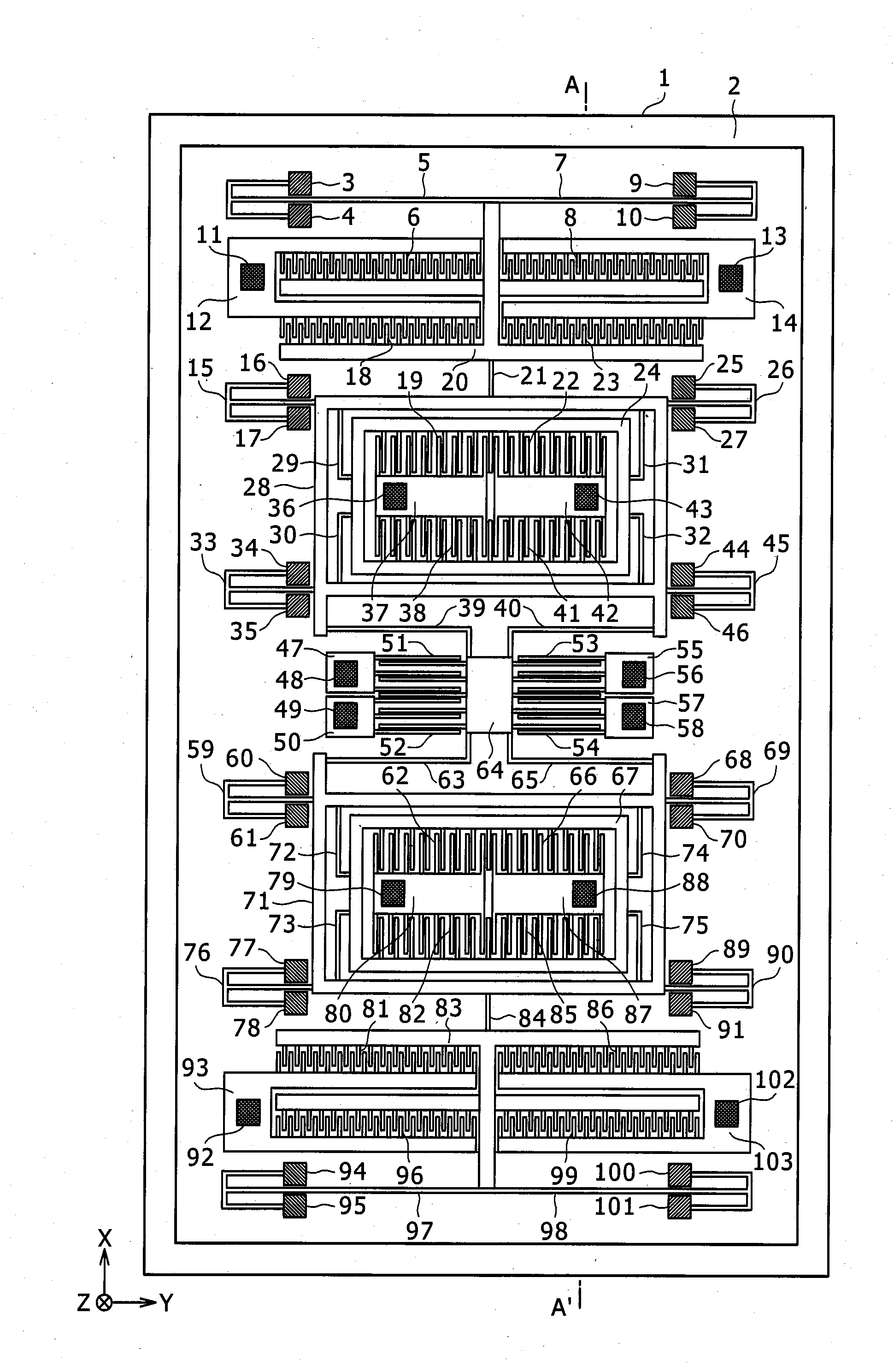
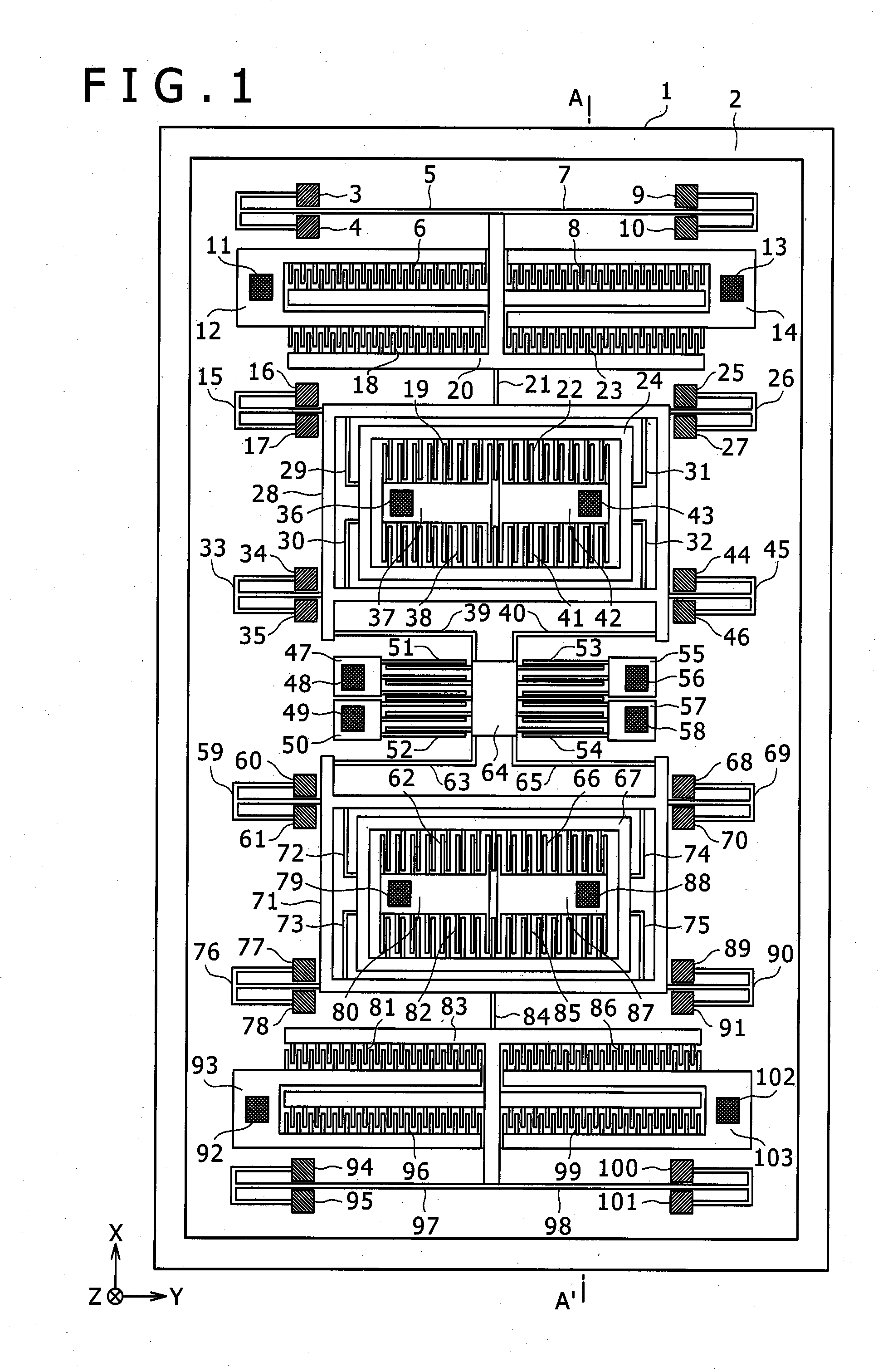
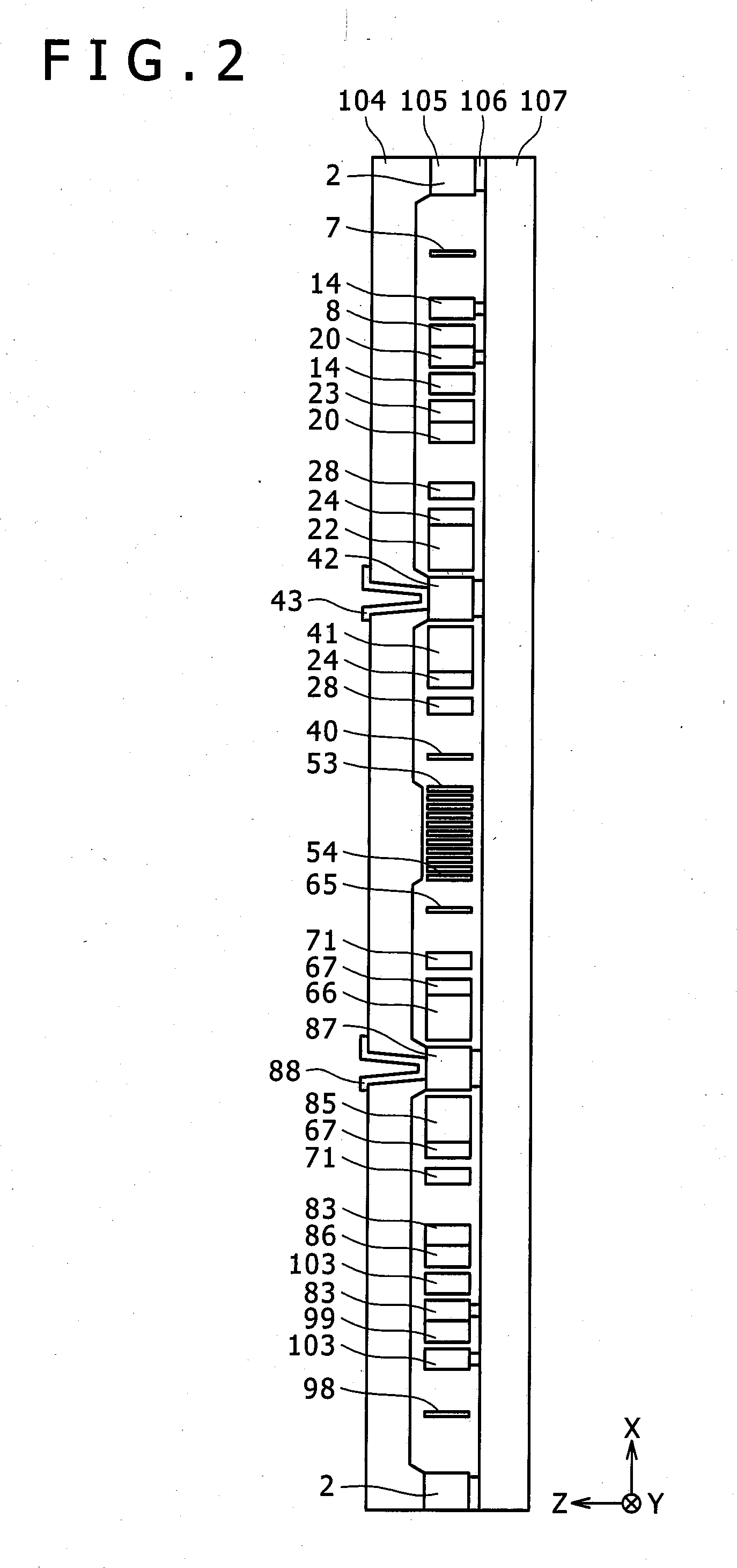
[0033]An angular velocity measuring device in a first embodiment according to the present invention will be described with reference to FIGS. 1 to 5. FIG. 1 is a plan view of a measuring element included in an angular velocity measuring device in a first embodiment according to the present invention, FIG. 2 is a sectional view taken on the line A-A′ in FIG. 1, FIG. 3 is a mechanical model of the measuring element included in the angular velocity measuring device in the first embodiment, FIG. 4 is a graph showing the frequency characteristic of the measuring element of the angular velocity measuring device in the first embodiment, and FIG. 5 is a circuit diagram of a drive circuit included in the angular velocity measuring device in the first embodiment.
[0034]A measuring element 1 included in the angular velocity measuring device in the first embodiment will be described with reference to FIGS. 1 and 2.
[0035]The measuring element 1 is formed by forming a longitudinal groove in a sili...
Example
[0048]An angular velocity measuring device in a second embodiment according to the present invention will be described with reference to FIG. 6 showing the angular velocity measuring device in the second embodiment in a plan view. The angular velocity measuring device in the second embodiment is provided with a measuring element 1 including a viscous force generating mechanism in a modification of the viscous force generating mechanism 112 included in the measuring element 1 of the angular velocity measuring device in the first embodiment. Referring to FIG. 6, the viscous force generating mechanism included in the measuring element 1 of the angular velocity measuring device in the second embodiment includes an elastic connecting beam 144 elastically connecting the outer frame 28 of the first oscillator and the outer frame 71 of the second oscillator, frames 143 and 145 spaced apart from the silicon substrate 107, frames 137, 139, 148 and 150 fixed to the silicon substrate 107, a par...
Example
[0049]An angular velocity measuring device in a third embodiment according to the present invention will be described with reference to FIG. 7 showing the angular velocity measuring device in the third embodiment in a plan view. The angular velocity measuring device in the second embodiment is provided with a measuring element 1 including a viscous force generating mechanism in a modification of the viscous force generating mechanism 112 included in the measuring element 1 of the angular velocity measuring device in the first embodiment. Referring to FIG. 7, the viscous force generating mechanism included in the measuring element 1 of the angular velocity measuring device in the third embodiment includes frames 153 and 160 spaced apart from the silicon substrate 107, a T-shaped elastic connecting beam 156 elastically connecting the outer frame 28 of the first oscillator to the frames 153 and 160, a T-shaped elastic connecting beam 165 elastically connecting the outer frame 71 of the...
PUM
Abstract
Description
Claims
Application Information
- R&D Engineer
- R&D Manager
- IP Professional
- Industry Leading Data Capabilities
- Powerful AI technology
- Patent DNA Extraction
Browse by: Latest US Patents, China's latest patents, Technical Efficacy Thesaurus, Application Domain, Technology Topic.
© 2024 PatSnap. All rights reserved.Legal|Privacy policy|Modern Slavery Act Transparency Statement|Sitemap