Frequency changer and digital tuner

a digital tuner and frequency changer technology, applied in digital transmission, phase-modulated carrier systems, pulse automatic control, etc., can solve the problems of re-radiation of local oscillator signals, not being able to form all the main tuner circuitry in a single integrated circuit, and being difficult to achieve the effect of reducing the cost of manufacture, improving the performance of the tuner, and good phase noise performan

Inactive Publication Date: 2005-05-17
INTEL CORP
View PDF7 Cites 13 Cited by
  • Summary
  • Abstract
  • Description
  • Claims
  • Application Information

AI Technical Summary

Benefits of technology

[0034]Such arrangements provide substantial improvements in tuner performance, for example making substantially fully integrated ZIF tuners with acceptable performance a practical possibility. The second oscillator can be phase-locked, for example by a low noise PLL frequency synthesiser incorporating the reference oscillator, and so has very good phase noise performance because it can be required to tune over a relatively narrow frequency range and hence have a high Q. By phase-locking the first oscillator to the second oscillator, the resulting local oscillator signal for mixing or multiplying with the input signal has very low phase noise and is resistant to injection pulling. For example, the feedback bandwidth of the control loop for the first oscillator can be arranged to be high enough to cover the bandwidth of the input signal so that the free-running phase noise of the first oscillator is greatly reduced by the phase-locking to the second oscillator. It is thus possible to provide, for example, a ZIF digital tuner which is suitable for DBS applications and which can be formed as a single monolithic integrated circuit with very few external or off-chip components.

Problems solved by technology

Although this known type of digital tuner provides acceptable performance, it is relatively complicated and relatively expensive to manufacture.
Although the ZIF tuner shown in FIG. 2 represents a substantial simplification compared with the tuner shown in FIG. 1, it is still not possible to form all of the main tuner circuitry in a single integrated circuit and achieve the necessary performance for acceptable results.
The problems with such a tuner architecture result from the fact that the local oscillator frequency in the frequency changer 13 is within the frequency band or channel of the desired input signal.
First, such leakage results in re-radiation of the local oscillator signal to other tuners which may be connected to the same antenna system or may be located nearby.
Because of phase shifts which are inherent in such leakage mechanisms and because of amplification within the ZIF tuner, this results in a DC imbalance at the outputs of the frequency changer 13.
Such a DC imbalance can represent a significant fraction of the desired signal and cannot be improved because of limits to the degree of isolation which is achievable.
The RF signal carries a pseudo random noise (PSRN) type modulation and appears like broadband noise, which is impressed on the oscillator signal and thus degrades the noise performance.
The degradation caused by injection pulling to the oscillator phase noise performance thus limits the application of ZIF techniques within DBS applications because lower data rates require a very pure local oscillator signal in order to achieve satisfactory performance.
In practice, in order to achieve satisfactory performance with ZIF techniques, a relatively low amplitude input signal must be supplied to the input of the ZIF circuit and this results in disadvantages such as reduced dynamic range.
However, such integrated oscillators have such inherently poor phase noise characteristics that they are totally unsuitable for use in DES receiving systems.
Also, such techniques have been applied to conventional super-heterodyning architectures but have not been applied to ZIF architectures.
However, this provides no improvement in phase noise outside the loop bandwidth.
Thus, the integrated phase noise outside this bandwidth has a significant detrimental effect on performance.

Method used


Image

  • Frequency changer and digital tuner
  • Frequency changer and digital tuner
  • Frequency changer and digital tuner

Examples


Embodiment Construction

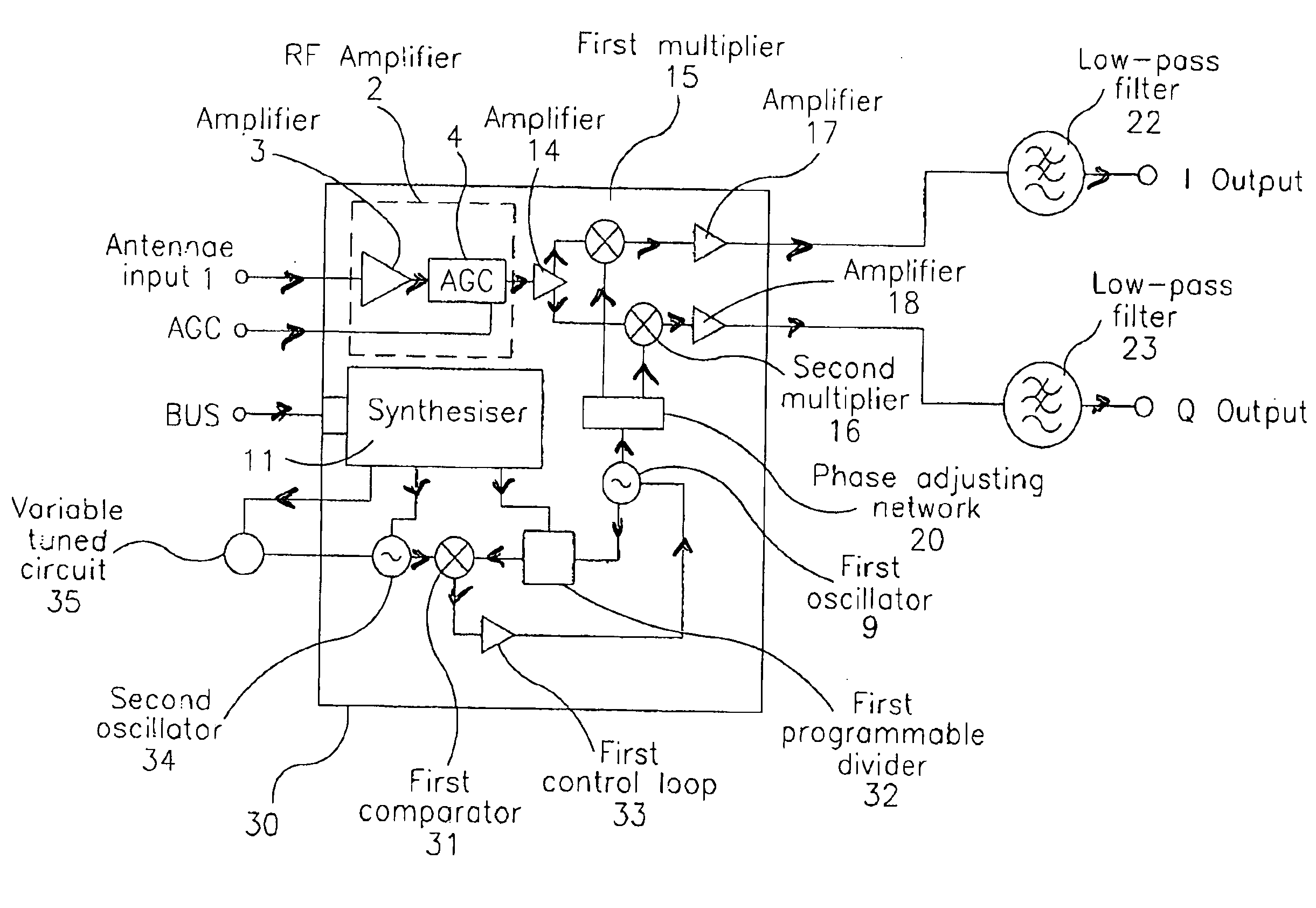
[0042]The digital tuner and frequency changer shown in FIG. 3 comprise a ZIF tuner for receiving and demodulating QPSK signals, for example in a DBS receiver system. The tuner receives input signals in an input frequency band which is typically from 950 to 2150 MHz. A plurality of channels are located within this input band, for example having centre frequencies which are equally spaced, for example at the Nyquist bandwidth.

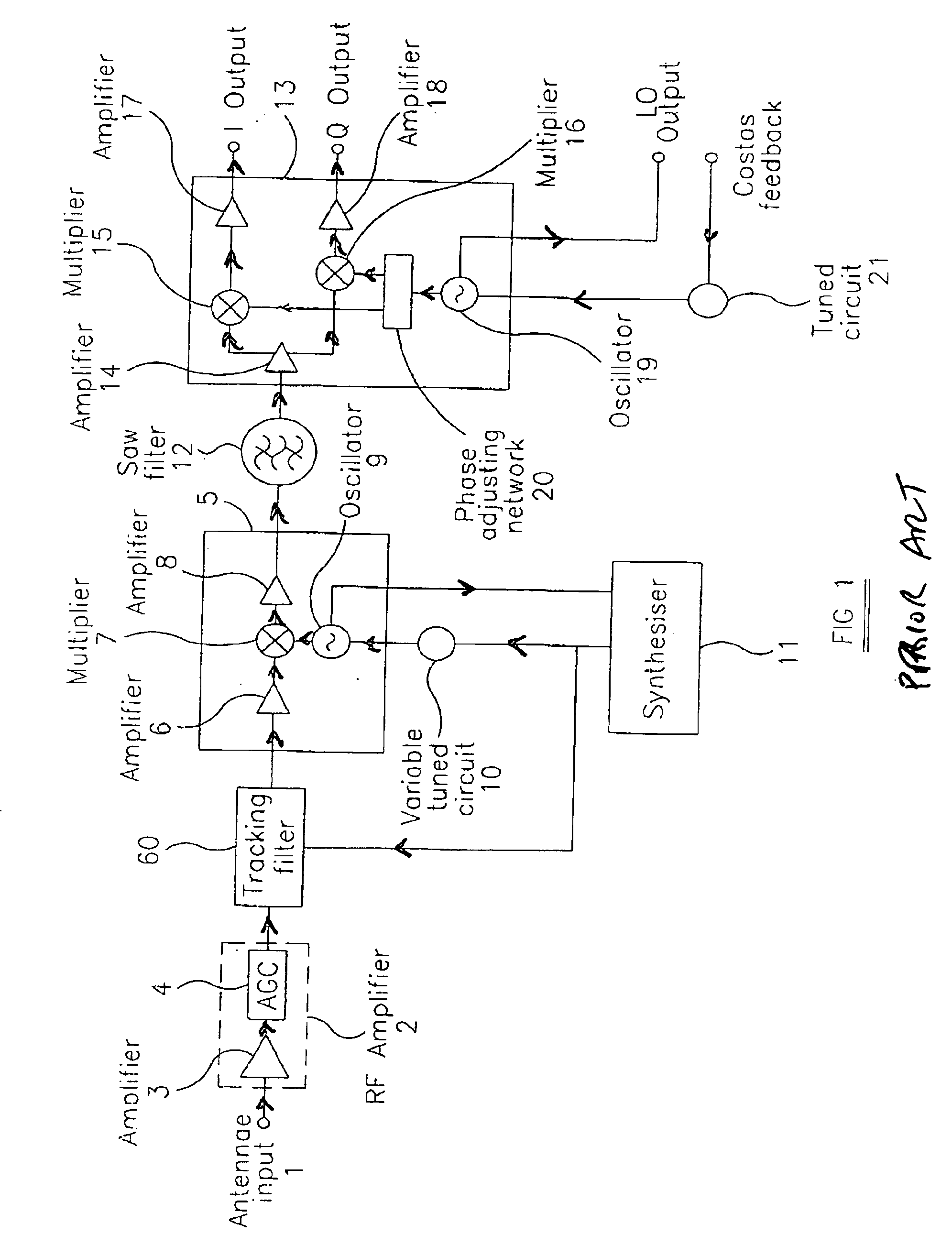
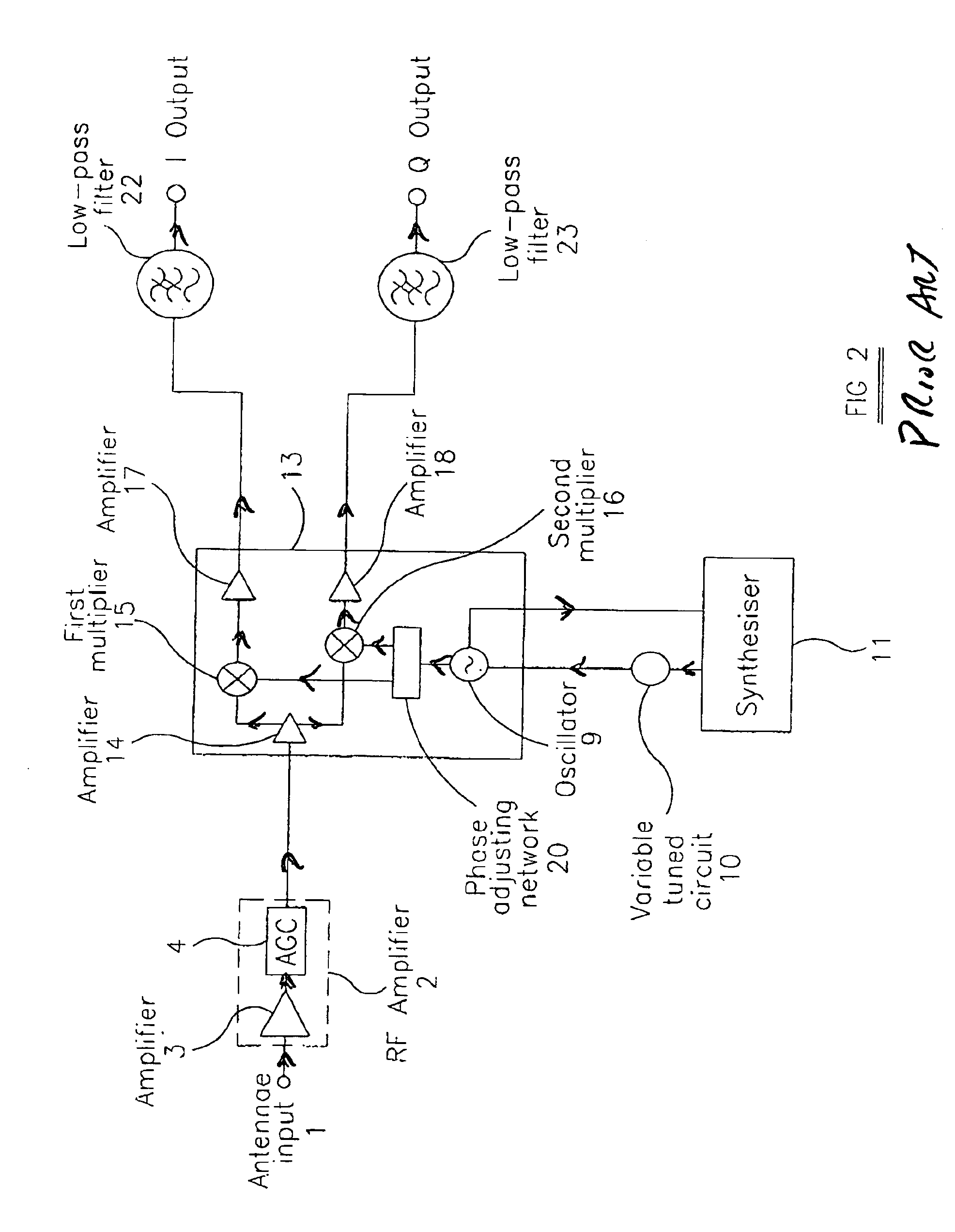
[0043]The tuner effectively comprises a frequency changer in the form of a single monolithic integrated circuit 30 with very few external components. The frequency changer is of the ZIF type and is similar to that shown in FIG. 2. Accordingly, those elements and components of the tuner shown in FIG. 3 which are the same as the corresponding elements and components shown in FIG. 2 will not be described again in detail.

[0044]The frequency changer 30 includes the RF amplifier 2 within the integrated circuit and has an AGC input for receiving a control voltage from a...


PUM


Abstract

A zero or near zero IF frequency changer for use in a digital tuner comprises multipliers which receive the RF input signal from an input. The multipliers receive quadrature local oscillator signals from a first oscillator of an arrangement which comprises first and second phase-locked loops. The first phase-locked loop comprises a programmable divider, a comparator and a control loop so that the first oscillator is phase-locked to a second oscillator. A second phase-locked loop comprises the second oscillator and a synthesizer containing a reference oscillator to which the second oscillator is phase-locked. The output frequency of the second oscillator is in a frequency band which is outside the RF input frequency band of the frequency changer.

Description

BACKGROUND OF THE INVENTION[0001]1. Field of the Invention[0002]The present invention relates to a frequency changer. Such a frequency changer may, for example, be used as part of a zero intermediate frequency (ZIF) tuner, for instance, for a digital direct broadcasting by satellite (DBS) receiver system. The present invention also relates to a digital tuner. In general, the invention may be applied to any tuner where a received channel contains a local oscillator frequency.[0003]2. Description of the Prior Art[0004]A known type of digital tuner for use in a DBS system is illustrated in FIG. 1 of the accompanying drawings and is based on the well-known super-heterodyning technique, which has been used in analogue tuners for many decades. An antennae input 1 for receiving an input signal from an antennae system is connected to the input of a radio frequency (RF) amplifier 2, which comprises a low noise amplifier 3 and an automatic gain control (AGC) arrangement 4. The RF amplifier 2 ...

Claims


Application Information

Patent Timeline
Patent Type & Authority Patents(United States)
IPC IPC(8): H03D3/00H03L7/23H03L7/16H04B1/28
CPCH03D3/007H04B1/28H03L7/23
Inventor COWLEY, NICHOLAS PMUDD, MARK S. J
Owner INTEL CORP
Why Eureka
Try Eureka