Disc brake assembly

a technology of disc brakes and components, applied in the direction of fluid actuated brakes, slack adjusters, braking elements, etc., can solve the problems of reducing the coefficient of friction needed for stopping power, releasing harmful particles into the atmosphere, and contaminating water streams

Active Publication Date: 2010-04-22
GELB JOSEPH
View PDF54 Cites 49 Cited by
  • Summary
  • Abstract
  • Description
  • Claims
  • Application Information

AI Technical Summary

Benefits of technology

[0006]In one aspect of the invention, a system is provided for increasing the air flow to a disc brake assembly, said system comprising a main housing, a drive shaft, said drive shaft positioned to be powered by a rotor from a disc brake assembly, at least one impeller, said impeller positioned to be powered by said drive shaft, said impeller capable of being turned to draw the airflow from a rotor of a disc b...

Problems solved by technology

Additionally, as brake pads erode, they release harmful particles into the atmosphere.
These harmful particles can also enter and pollute water streams.
This is because at high temperatures, the coefficient of friction needed for stopping power is reduced and brake performance is consequently diminished.
The waste particles that are released into the atmosphere from brake pads also creates multiple dilemmas.
This material is known as brake dust and can be problematic...

Method used


Image

  • Disc brake assembly
  • Disc brake assembly
  • Disc brake assembly

Examples


Embodiment Construction

[0039]The following discussion describes in detail one embodiment of the invention and several variations of that embodiment. This discussion should not be construed, however, as limiting the invention to those particular embodiments. Practitioners skilled in the art will recognize numerous other embodiments as well.

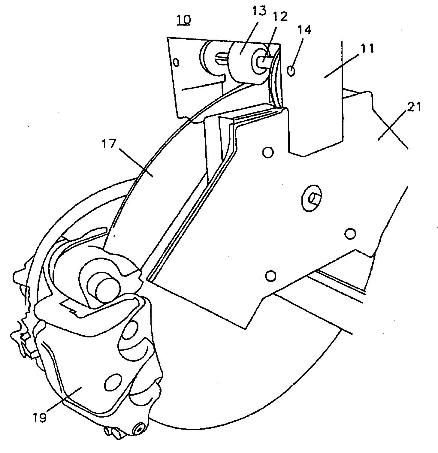
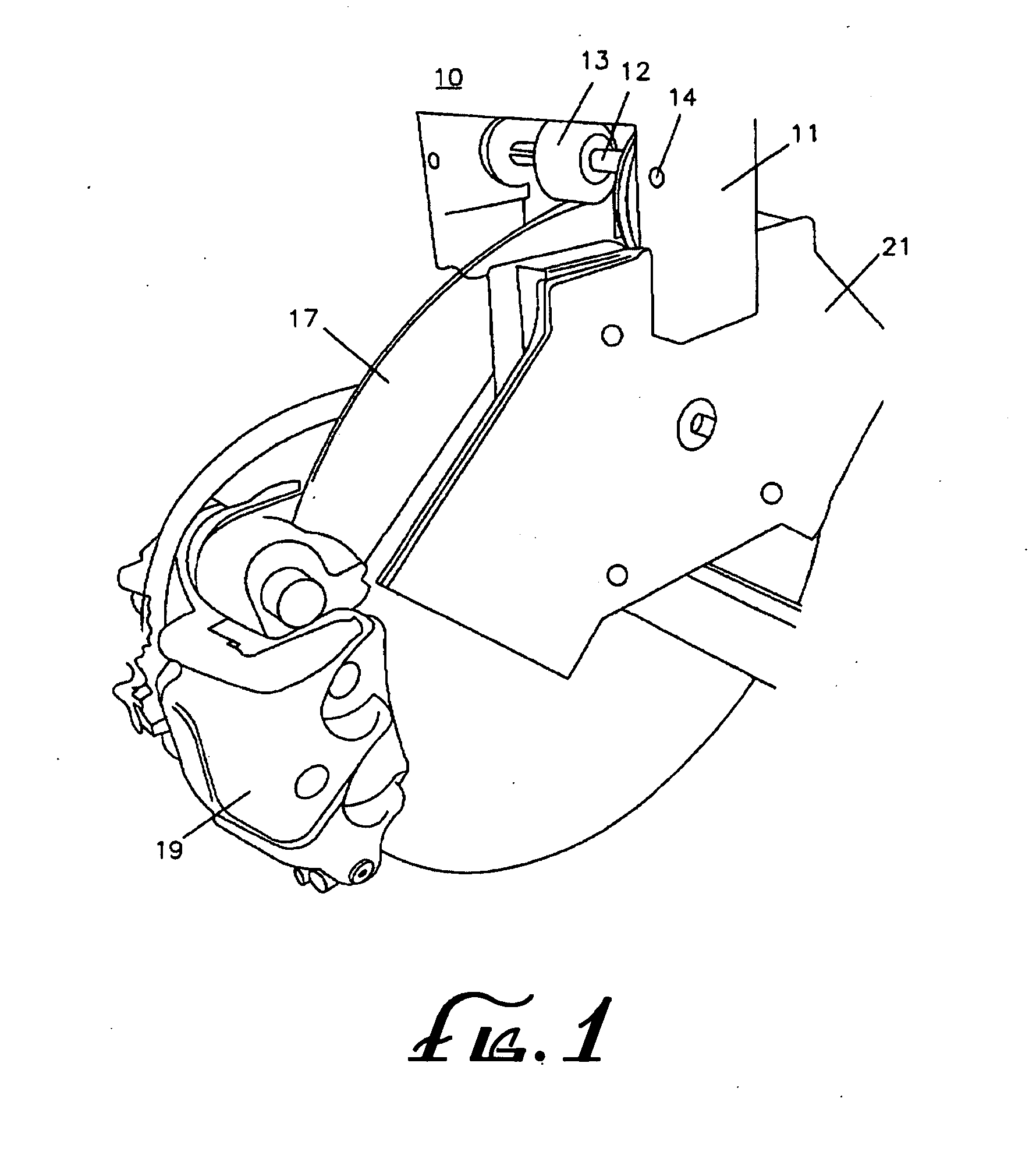
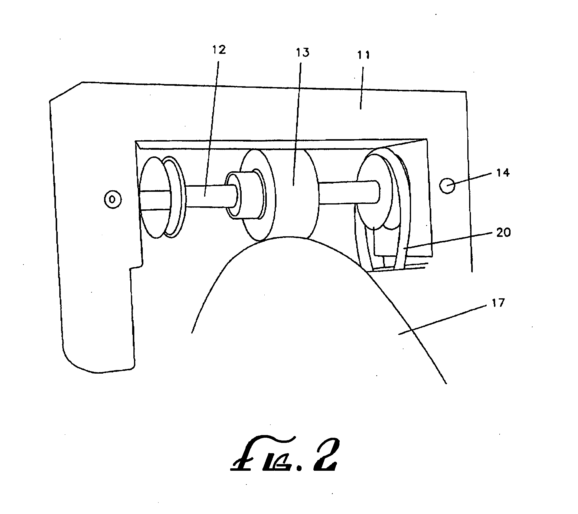
[0040]Referring to FIGS. 1-10, in one aspect of the invention, a system is provided for increasing the air flow to a disc brake assembly 10. The system comprises a main housing 11 and a drive shaft 12. The drive shaft 12 is positioned to be powered by a rotor 17 from the disc brake assembly 10. The disc brake assembly 10 further comprises at least one impeller 15, the impeller 15 is positioned to be powered by the drive shaft 12 and is capable of being rotated to draw airflow from the rotor 17. The disc brake assembly 10 still further comprises at least one impeller housing 21. The impeller housing 21 is adapted to house the impeller 15 and can define an airflow inlet 22...


PUM


Abstract

A disc brake assembly includes a rotor, a caliper, brake pads and an optional filter. The optional filter can be disposed within a shroud which covers at least about 70% of the distal side periphery on at least one of the two sides of the rotor. The disc brake also includes an impeller or other means for providing air flow to the disc brake assembly. The impeller can be provided by the rotor itself or it can be provided by a separate component which is powered either directly or indirectly by the rotor.

Description

FIELD OF THE INVENTION[0001]The present invention is directed to a disc brake assembly and, in some embodiments, to a system for cooling disc brakes and / or for collecting friction material waste particle discharge from brake pads in disc brake assemblies.BACKGROUND OF THE INVENTION[0002]Disc brake systems are the most common form of braking mechanisms used today for vehicle wheels and most specifically for mass produced motorcycles and automobiles. Disc braking systems work by utilizing brake pads which are compressed against a rotor (also called a disc) to slow down a vehicle's wheels. As a by-product of this system, a large amount of heat is released as the kinetic energy from the wheel momentum is converted by the friction created by the brake pads. Additionally, as brake pads erode, they release harmful particles into the atmosphere. These harmful particles can also enter and pollute water streams. The present invention addresses and alleviates these common problems.[0003]Coolin...

Claims


Application Information

Patent Timeline
IPC IPC(8): F16D65/78F16D55/02
CPCF16D65/847F16D65/0031
Inventor GELB, JOSEPH
Owner GELB JOSEPH
Why Eureka
Try Eureka