Red-Emitting Luminophore and Light Source Comprising such a Luminophore

a luminophore and red-emitting technology, which is applied in the direction of luminescent compositions, chemistry apparatuses and processes, etc., can solve the problems of poor thermal stability of the luminescence and the disadvantage of broadband emission, and achieve the effect of increasing the number of times and improving the radiation stability

Active Publication Date: 2010-04-22
OSRAM OLED
View PDF9 Cites 11 Cited by
  • Summary
  • Abstract
  • Description
  • Claims
  • Application Information

AI Technical Summary

Benefits of technology

[0011]Even the quantum efficiency an...

Problems solved by technology

As in the case of the nitrides, the previously known systems are distinguished by very high efficiency and thermal stability, but have the disadvantage of the broadband emission.
Althoug...

Method used


Image

  • Red-Emitting Luminophore and Light Source Comprising such a Luminophore
  • Red-Emitting Luminophore and Light Source Comprising such a Luminophore

Examples


Embodiment Construction

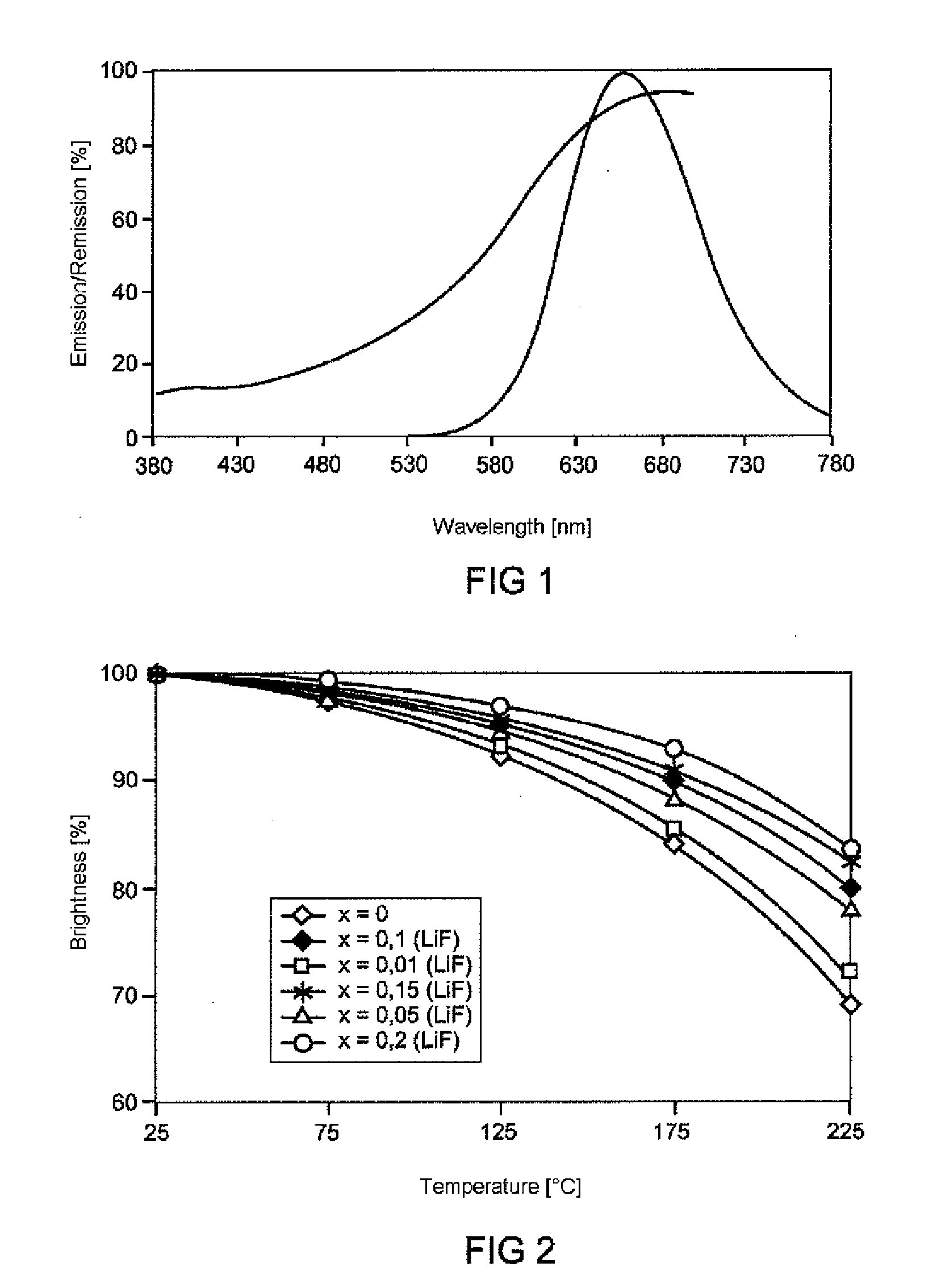
[0016]FIG. 1 shows the emission and reflection spectrum of a fluoridated calsin phosphor having the nominal composition in the sense of batch stoichiometry Ca0.88Eu0.02Li0.1AlSi(N0.967F0.033)3. The emission maximum is approximately 655 nm.

[0017]FIG. 2 shows the thermal quenching behavior for various LiF proportions as a function of the temperature. Curve 1 is calsin Ca0.98Eu0.02AlSiN without admixture of LiF. Curve 2 shows the stability of a calsin with 1 mol % proportion of Li in M, where here M=Ca. Curve 3 shows 5 mol % proportion of Li in M and curve 4 shows 10 mol % proportion of Li in M. It holds true here in each case that identical molar amounts F likewise become incorporated for N, in the sense of the formula above.

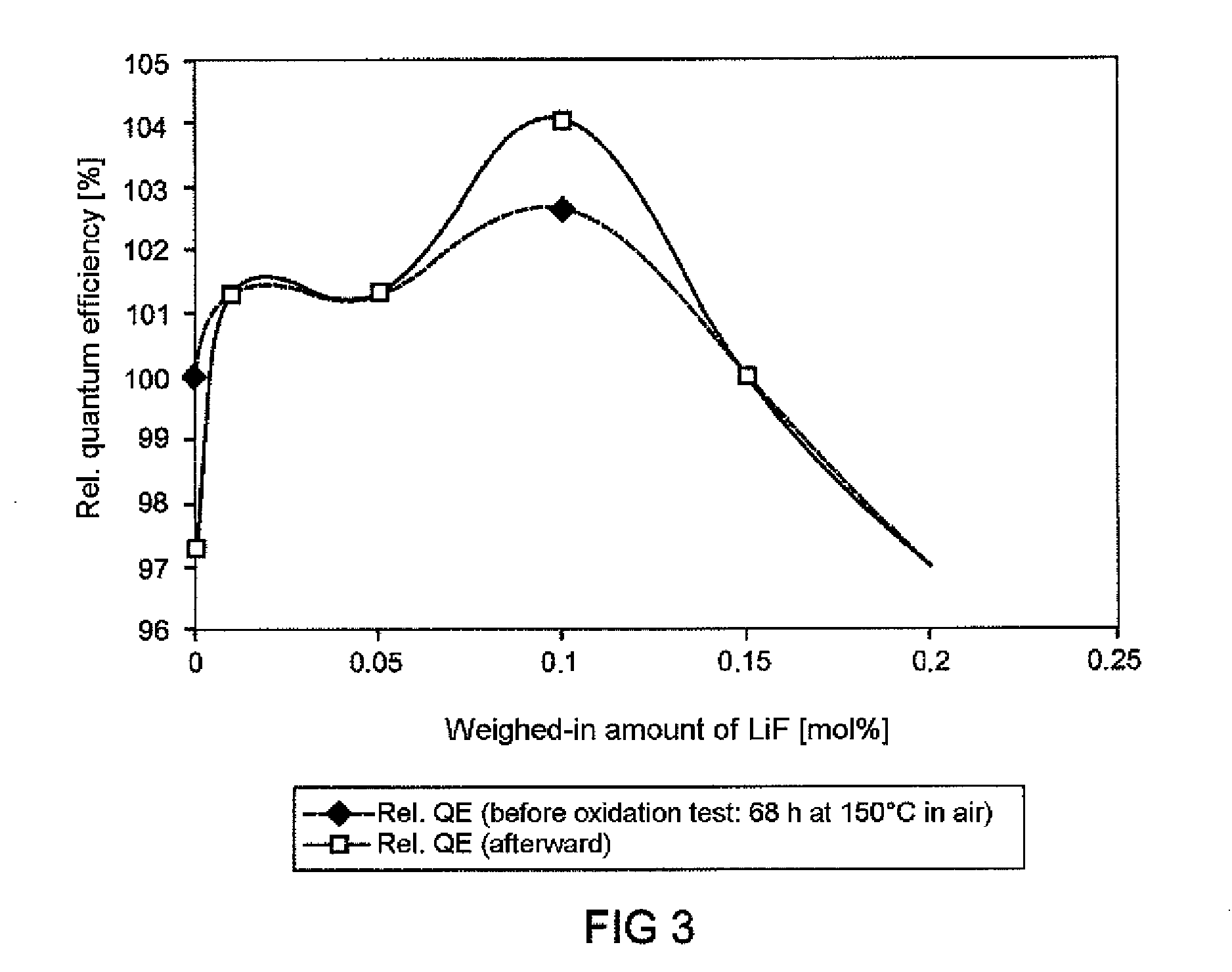
[0018]FIG. 3 shows the effect of the weighed-in amount of LiF on the oxidation stability of the calsin phosphor. A complex pattern of behavior is manifested here. The illustration shows the relative quantum efficiency before the oxidation test (dashed line) and af...


PUM


Abstract

A red-emitting phosphor composed of an M—Al—Si—N system, comprising a cation M, wherein M is represented by at least one of the elements Ca or Ba or Sr and, if appropriate, can additionally be combined with at least one further element from the group Mg, Zn, Cd, wherein the phosphor is activated with Eu, which partly replaces M, and wherein the phosphor additionally contains LiF

Description

TECHNICAL FIELD[0001]The invention is based on a red-emitting phosphor, preferably for use in light sources, in accordance with the preamble of claim 1. The invention relates to a highly efficient phosphor from the class of nitridosilicates in accordance with the preamble of claim 1. The invention furthermore relates to a light source produced therewith and a method for producing such a phosphor.PRIOR ART[0002]EP-A 1 568 753 and EP-A 1 614 738 disclose a phosphor which emits in the red and has the composition MSiAlN3:Z. In this case, M is principally Ca and the activator Z is principally Eu. They are referred to here as calsins. Said phosphor can be excited well in the UV and blue spectral range. It is suitable for light sources such as LEDs.[0003]EP-A 1 153 101 discloses a red-emitting phosphor of the type nitride M2Si5N8:Eu, wherein M can be Ca inter alia, and the activator is Eu.SUMMARY OF THE INVENTION[0004]The object of the present invention is to specify a narrowband, thermall...

Claims


Application Information

Patent Timeline
IPC IPC(8): C09K11/77C09K11/54
CPCC09K11/7734C09K11/0883C09K11/77348C09K11/77
Inventor BECKER, DANIELFIELDER, TIMJERMANN, FRANKPOHL, BIANCAZACHAU, MARTIN
Owner OSRAM OLED
Why Eureka
Try Eureka