Quantum dots in enclosed environment

a quantum dots and enclosed environment technology, applied in the field of lighting devices, can solve the problems of less than desirable, less than general desired, less than desirable, and less good barrier against oxygen or water in ambient conditions, and achieve the effects of improving the emission efficiency of dots, high efficiency, and increasing the efficacy of led based lamps

Active Publication Date: 2018-12-18
LUMILEDS
View PDF4 Cites 0 Cited by
  • Summary
  • Abstract
  • Description
  • Claims
  • Application Information

AI Technical Summary

Benefits of technology

[0005]Quantum dots (qdots or QDs) are currently being studied as phosphors in solid state lighting (SSL) applications (LEDs). They have several advantages such as a tunable emission and a narrow emission band which can help to significantly increase the efficacy of LED based lamps, especially at high CRI. Typically, qdots are supplied in an organic liquid, with the quantum dots surrounded by organic ligands, such as oleate (the anion of oleic acid), which helps to improve the emission efficiency of the dots as well as stabilize them in organic media. The synthesis of silica coatings on quantum dots is known in the art. Koole et al. (in R. Koole, M. van Schooneveld, J. Hilhorst, C. de Mello Donegá, D. 't Hart, A. van Blaaderen, D. Vanmaekelbergh and A. Meijerink, Chem. Mater, 20, p. 2503-2512, 2008) describes experimental evidence in favor of a proposed incorporation mechanism of hydrophobic semiconductor nanocrystals (or quantum dots, QDs) in monodisperse silica spheres (diameter ˜35 nm) by a water-in-oil (W / O) reverse microemulsion synthesis. Fluorescence spectroscopy is used to investigate the rapid ligand exchange that takes place at the QD surface upon addition of the various synthesis reactants. It was found that hydrolyzed TEOS has a high affinity for the QD surface and replaces the hydrophobic amine ligands, which enables the transfer of the QDs to the hydrophilic interior of the micelles where silica growth takes place. By hindering the ligand exchange using stronger binding thiol ligands, the position of the incorporated QDs could be controlled from centered to off-center and eventually to the surface of the silica spheres. They were able to make QD / silica particles with an unprecedented quantum efficiency of 35%. Silica encapsulation of QDs, see also above, is (thus) used to stabilize the QDs in air and to protect them from chemical interactions with the outside. The reverse micelle method was introduced in the 90's as a method to make small (˜20 nm) silica particles with a small size dispersion (see below). This method can also be used to make silica-coated QDs. The native organic ligands around QDs are replaced by inorganic silica precursor molecules during the silica shell growth. The inorganic silica shell around QDs has the promise to make QDs more stable against photo-oxidation, because the organic ligands are seen as the weak chain in conventional (e.g. oleic acid or hexadecylamine) capped QDs.
[0008]It was surprisingly observed that silica coated QDs require a certain amount of water to ensure optimal performance (both QE and stability). Especially when QDs are used within a hermetically sealed light bulb, it surprisingly appears that it is important to include a sufficient amount of water. A specific example of such an application is a helium cooled LED bulb, where a number of LEDs are placed in a hermetically sealed glass bulb (using the process used for conventional incandescent light bulbs) under a helium atmosphere. Because of the unique cooling properties of helium, limited additional heat sinking is required in such a lamp architecture, saving significant costs. However, when QDs are used in such a closed, water-free environment, it is seen that the overall performance is worse than in ambient, and increased initial quenching and photo brightening effects are observed. It was surprisingly found that adding a significant relative humidity (at room temperature) to the sealed environment in which QDs are enclosed (e.g. a He or He / O2 filled light bulb) prevents especially initial quenching and photobrightening effects.
[0014]Optionally, the lighting device further comprises a heat sink in thermal contact with one or more of the transmissive window, the light source and the wavelength converter. Together with the filling gas, this may provide a good thermal control and will reduce operating temperature. The term “thermal” contact may in an embodiment mean physical contact and may in another embodiment mean in contact via a (solid) thermal conductor.
[0032]Hence, it appears that helium as atmosphere, and / or optionally one or more other high thermal conductivity gas(ses), for the quantum dots is beneficial. Especially the helium gas and / or other gasses are used for cooling. Cooling is important for LED efficiency. Especially also for QD-based LEDs, a lower temperature will in general mean longer stability (lifetime) and higher lm / W efficiency (due to higher QE). However, surprisingly the presence of some H2O is further beneficial. In a specific embodiment at least 70% (not including H2O), such as especially at least 75%, such as at least 80%, of the filling gas consists of He. The percentage refers to volume percentages. Further, the presence of some oxygen may surprisingly also be beneficial. Hence, would in the past solutions be sought that try to seal as good as possible the quantum dots from water and oxygen, in the present invention deliberately some water, and optionally also some oxygen, is provided into the chamber wherein the quantum dots are arranged. In yet a further embodiment, the filling gas comprises (at least) helium and oxygen. In a specific embodiment, at least 95%, such as at least 99% of the filling gas (not taking into account H2O) consists of He and O2, and wherein the gas comprises at maximum 30% oxygen, such as at maximum 25% oxygen, like at maximum 20% oxygen. Larger amounts of oxygen may be less desirable in view of amongst others thermal energy management and also stability of the lighting device. Other gasses that may be available may be selected from the (other) noble gasses, H2 and N2, especially H2 and N2. As indicated above, the RH is at least 1%, even more at least 5%, such as at least 10%. Especially, at 19° C. the chamber does not contain liquid water.
[0035]On such outer layer, a (silica) coating may be provided, thereby providing a bare quantum dot with a (silica) coating or a core-shell quantum dot with a (silica) coating. Coating quantum dots with silica results in replacement of the organic ligands by silica precursor molecules, which may act as more stable inorganic ligands. In addition, the silica layer may form a protective barrier against e.g. photo-oxidative species. Especially, the coating entirely covers the outer layer. Suitable methods to provide silica coatings around QDs are amongst others described by Koole et al. (see above), and references cited therein. The synthesis of silica particles without nanoparticles enclosed was first developed by Stober et al (J. Colloid Interface Sci. 1968, 62), which allows the growth of silica spheres of uniform size and shape in e.g. an ethanol phase. The second method of making silica spheres uses micelles in an apolar phase and is called the reverse micelle method (or reverse micro emulsion method), and was first suggested by Osseo-Asare, J. Colloids. Surf 1990, 6739). The silica particles are grown in defined water droplets, which results in a uniform size distribution which can be controlled quite easily. This approach was extended by introducing nanoparticles in the silica. The main advantage of this approach compared to the Stober method, is that both hydrophobic and hydrophilic particles can be coated, no ligand exchange on forehand is required and there is more control over the particles size and size dispersion.

Problems solved by technology

However, silica as grown by the reverse micelle method appears to be relatively porous, making it a less good barrier against oxygen or water than sometimes suggested.
For QDs with organic ligands the stability in ambient conditions is less than in general desired, and it was found that especially water is the root cause for degradation of such QDs.
This may lead to quantum dot based lighting devices which have a quantum efficiency (QE) stability and / or color point stability over time which are less than desirable.
Because of the unique cooling properties of helium, limited additional heat sinking is required in such a lamp architecture, saving significant costs.
However, when QDs are used in such a closed, water-free environment, it is seen that the overall performance is worse than in ambient, and increased initial quenching and photo brightening effects are observed.

Method used


Image

  • Quantum dots in enclosed environment
  • Quantum dots in enclosed environment
  • Quantum dots in enclosed environment

Examples


Embodiment Construction

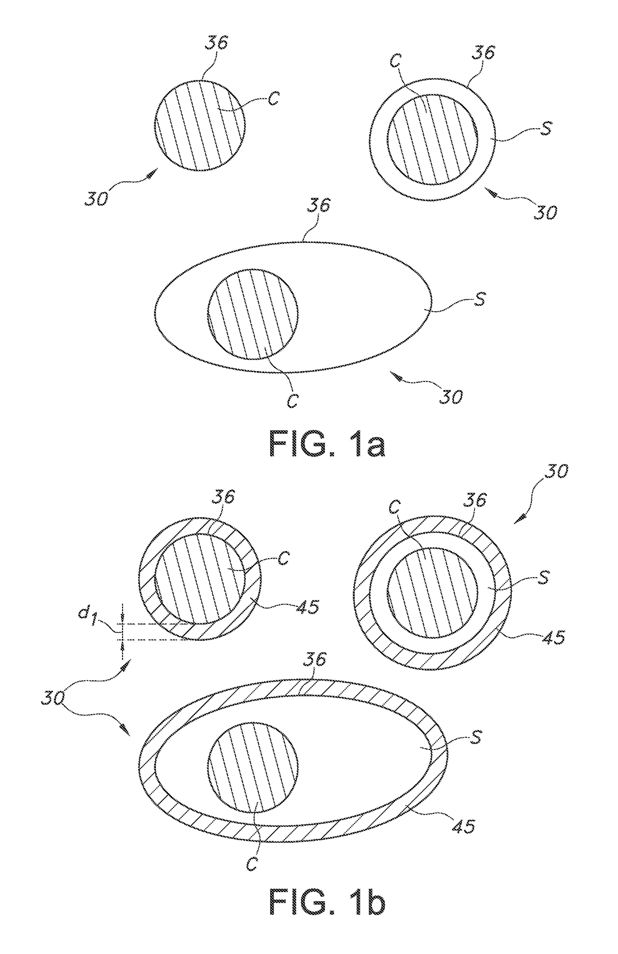
[0074]FIG. 1a schematically depicts a quantum dot based luminescent material. By way of example different types of QDs, indicated with reference 30, are depicted. The QD at the top left is a bare QD, without shell. The QD is indicated with C (core). The QD 30 at the right top is a core-shell particle, with C again indicating the core, and S indicating the shell. At the bottom, another example of a core-shell QD is schematically depicted, but a quantum dot in rod is used as example. Reference 36 indicates the outer layer, which is in the first example the core material at the external surface, and which is in the latter two embodiments the shell material at the external surface of the QD 30.

[0075]FIG. 1b schematically depicts an embodiment of the luminescent material, but now the QDs 30 including the coating 45, especially an oxide coating, such as a silica coating. The thickness of the coating is indicated with reference d1. The thickness may especially be in the range of 1-50 nm. E...


PUM


Abstract

The invention provides a lighting device for providing light, the lighting device comprising a closed chamber with a light transmissive window and a light source configured to provide light source radiation into the chamber, wherein the chamber further encloses a wavelength converter configured to convert at least part of the light source radiation into wavelength converter light, wherein the light transmissive window is transmissive for the wavelength converter light, wherein the wavelength converter comprises luminescent quantum dots which upon excitation with at least part of the light source radiation generate at least part of the wavelength converter light, and wherein the closed chamber comprises a filling gas comprising one or more of helium gas, hydrogen gas, nitrogen gas or oxygen gas, the filling gas having a relative humidity at 19° C. of at least 5%.

Description

CROSS-REFERENCE TO RELATED APPLICATIONS[0001]The present application is a § 371 application of International Application No. PCT / EP2015 / 071245 filed on Sep. 16, 2015 and entitled “QUANTUM DOTS IN ENCLOSED ENVIRONMENT,” which claims the benefit of U.S. Provisional Patent Application No. 62 / 057,334 filed on Sep. 30, 2014 and European Patent Application No. 14189526.8 filed on Oct. 20, 2014. International Application No. PCT / EP2015 / 071245, U.S. Provisional Patent Application No. 62 / 057,334, and European Patent Application No. 14189526.8 are incorporated herein.FIELD OF THE INVENTION[0002]The invention relates to a lighting device including luminescent nanoparticles. The invention further relates to the production process of such lighting device.BACKGROUND OF THE INVENTION[0003]The sealing of luminescent nanocrystals in lighting devices is known in the art. WO2011 / 053635, for instance, describes a light-emitting diode (LED) device, comprising: (a) a blue-light emitting LED; and (b) a he...

Claims


Application Information

Patent Timeline
Patent Type & Authority Patents(United States)
IPC IPC(8): F21K9/64F21V29/70F21V9/30F21V31/00F21K9/23F21K9/232F21Y101/00F21Y115/10
CPCF21K9/64F21K9/23F21K9/232F21V29/70F21V31/00F21V9/30F21Y2115/10F21Y2101/00F21V9/32F21V9/45F21V9/08
Inventor KOOLE, ROELOFVELDMAN, DIRKBOHMER, MARCEL RENESHIMIZU, KENTAROKOOPMANS, LOES JOHANNA MATHILDATIMMERING, CORNELIS EUSTATIUS
Owner LUMILEDS
Why Eureka
Try Eureka