Micromechanical element and sensor for monitoring a micromechanical element

a micromechanical element and sensor technology, applied in the direction of piezoelectric device force measurement, control mechanism, element comparison, etc., can solve the problems of comparatively high power consumption, high drive voltage, electromechanical instabilities, etc., and achieve low space requirements, low power dissipation, and the effect of reducing the space requirements of the driv

Active Publication Date: 2010-04-22
FRAUNHOFER GESELLSCHAFT ZUR FOERDERUNG DER ANGEWANDTEN FORSCHUNG EV
View PDF8 Cites 19 Cited by
  • Summary
  • Abstract
  • Description
  • Claims
  • Application Information

AI Technical Summary

Benefits of technology

[0020]Several embodiments according to the invention are based on the basic idea that integrating a piezoelectric drive in or on a retaining element of the functional element of the micromechanical element minimizes the space requirements for the drive of the micromechanical element. Apart from the low space requirements, a drive based on the inverse piezoelectric effect has very low power dissipation and the drive voltages that may be used are low compared to other driving configurations, e.g. an electrostatic drive.
[0021]Further embodiments according to the invention are based on the basic idea that several retaining elements that are arranged symmetrically can reduce dynamic deformation of the functional element of the micromechanical element and that integrating the drive of the functional element of the micromechanical element in or on the retaining element of the functional element allows reducing the space requirements of the micromechanical element. Thereby, a high-quality micromechanical element can be provided in a compact manner and, thus, also in a cost-effective manner.
[0022]Several further embodiments according to the invention are based on the basic idea that a sensor for monitoring a micromechanical element can be realized by integrating a sensor element in a retaining element of the functional element of the micromechanical element. Since a movement of the functional element causes deformation of the retaining element, the deformation of the retaining element can be detected by a sensor element arranged in or on the retaining element and, thus, the movement of the functional element can be monitored. By integrating the sensor element in or on the retaining element, additional space requirements can be minimized.

Problems solved by technology

Disadvantages of electrostatic drives are, for example, the high drive voltages which may be frequently used as well as the occurring electromechanical instabilities.
Disadvantages of this principle are the comparatively high power consumption and the high technological effort (realizing crossings on the device).
In the case of micromechanical tilting mirrors, for example, there is the problem of converting the realized bending moments to a torque, such that the micro mirror can be deflected.
Existing solutions are often characterized by large space requirements.
This causes, for example, increasing space requirements of a device and, thus, increased production costs and limited integrability.

Method used


Image

  • Micromechanical element and sensor for monitoring a micromechanical element
  • Micromechanical element and sensor for monitoring a micromechanical element
  • Micromechanical element and sensor for monitoring a micromechanical element

Examples


Embodiment Construction

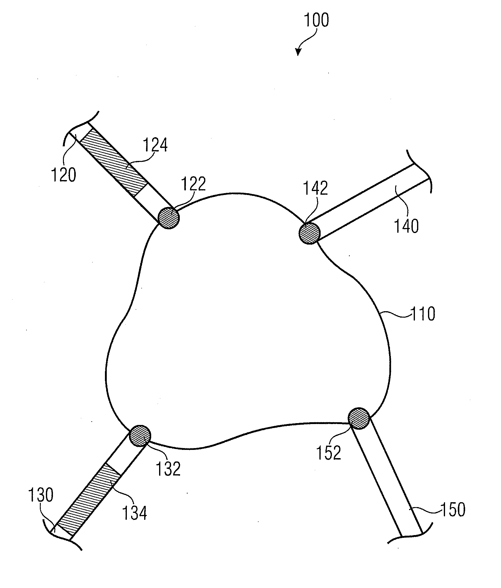
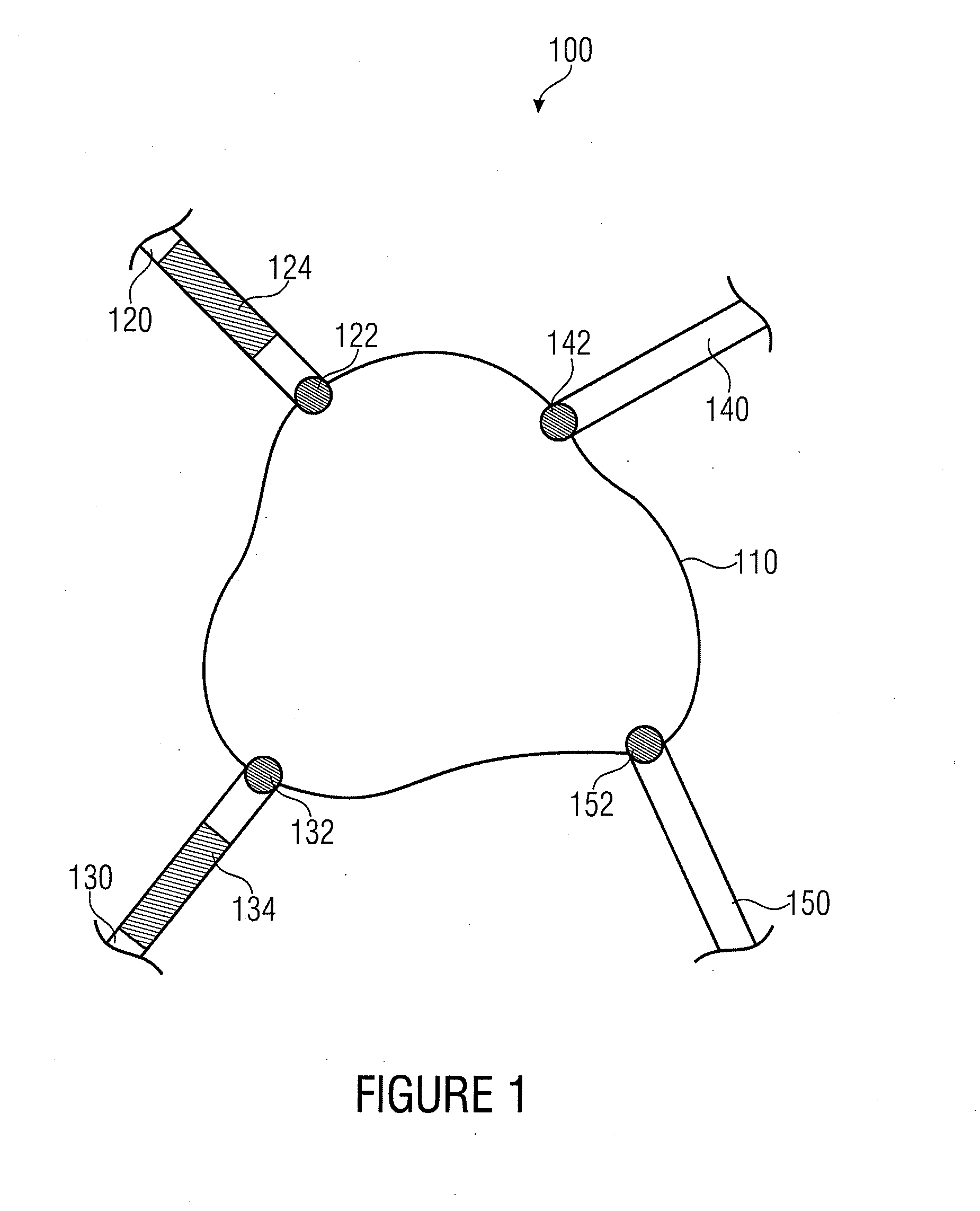
[0038]FIG. 1 shows a schematic representation of a micromechanical element 100 according to an embodiment of the invention. The micromechanical element 100 comprises a movable functional element 110, a first retaining element 120, a second retaining element 130, a third retaining element 140 and a fourth retaining element 150. Thereby, the first retaining element 120 and the functional element 110 are connected at a first junction 122, the second retaining element 130 and the functional element 110 at a second junction132, the third retaining element 140 and the functional element 110 at a third junction 142, and the fourth retaining element 150 and the functional element 110 at a fourth junction 152. Further, the first retaining element 120 and the second retaining element 130 each have one piezoelectric driving element 124, 134. The driving element 124 of the first retaining element 120 and the driving element 134 of the second retaining element 130 are implemented for moving the ...


PUM

PropertyMeasurementUnit
drive voltagesaaaaaaaaaa
electric excitationaaaaaaaaaa
frequencyaaaaaaaaaa

Abstract

A micromechanical element includes a movable functional element, a first retaining element, a second retaining element, a third retaining element, and a fourth retaining element. The first retaining element and the functional element are connected at a first junction, the second retaining element and the functional element are connected at a second junction, the third retaining element and the functional element are connected at a third junction, and the fourth retaining element and the functional element are connected at a fourth junction. In addition, the first retaining element and the second retaining element each include a piezoelectric driving element, the driving element of the first retaining element and the driving element of the second retaining element being configured to move the functional element in accordance with electric excitation.

Description

CROSS-REFERENCE TO RELATED APPLICATIONS[0001]This application claims priority from German Patent Application No. 102008049647.2, which was filed on Sep. 30, 2008, and is incorporated herein in its entirety by reference.[0002]Embodiments according to the invention relate to a micromechanical element and a sensor for monitoring a micromechanical element, as well as to a method of operating a micromechanical element and a method of monitoring a micromechanical element.[0003]Further embodiments according to the invention relate to a micromechanical device having a compact drive and / or piezodrive (piezoelectric driving element).BACKGROUND OF THE INVENTION[0004]For example, in micromechanical tilting mirrors, a mirror plate suspended at torsion springs is deflected by one (1D scanner) or two (2D scanner) axes. The drive can, for example, be realized by electrodes arranged in a comb-like manner, which are formed in the substrate level of the device, such as shown in “Schenk, H.: Ein neuart...

Claims


Application Information

Patent Timeline
Patent Type & Authority Applications(United States)
IPC IPC(8): G02B26/10B81B7/02B81B3/00B81B5/00G05B1/06H02N2/06H01L41/09G01L1/16
CPCB81B3/0062Y10T74/20341B81B2201/032
Inventor KLOSE, THOMASGRASSHOFF, THOMASCONRAD, HOLGER
Owner FRAUNHOFER GESELLSCHAFT ZUR FOERDERUNG DER ANGEWANDTEN FORSCHUNG EV
Why Eureka
Try Eureka