Homodyne receiver for optical communications with post processing

a receiver and optical communication technology, applied in electromagnetic receivers, electrical equipment, electromagnetic transmission, etc., can solve the problems of not being able to recover the phase of the optical signal, the disadvantage of high-coherent lasers and optical phase-locked loops, and the noise of unwanted changes of signals, so as to achieve the effect of maximizing the quality of the tun

Inactive Publication Date: 2010-04-22
UNIV POLITECNICA DE CATALUNYA
View PDF9 Cites 21 Cited by
  • Summary
  • Abstract
  • Description
  • Claims
  • Application Information

AI Technical Summary

Benefits of technology

[0026]It should be noted that the local laser advantageously includes a circuit or system for monitoring the optical carrier to compensate possible drifts in laser wavelengths, transmitter or local, as well as a circuit or optical channel tuning control system, to tune a new wavelength or optical frequency. For this setting, the laser can take a local control signal error or feedback from somewhere in the receiver, enabling it to continually maximize the quality of the tune.

Problems solved by technology

The main drawbacks of optical direct detection are the selection of optical channel and the noise, meaning noise any unwanted change of the signal that carries information on the communications system.
It is also noteworthy that these receivers are not able to recover the phase of the optical signal.
Importantly, homodyne detection improves the performances of an optical receiver, like sensitivity and frequency selectivity of the optical transmission, but has the disadvantage of needing lasers highly coherent and an optical phase-locked loop (oPLL).
This oPLL is a device that still is at experimental stage, having a complex design and a high cost.

Method used


Image

  • Homodyne receiver for optical communications with post processing
  • Homodyne receiver for optical communications with post processing

Examples


Embodiment Construction

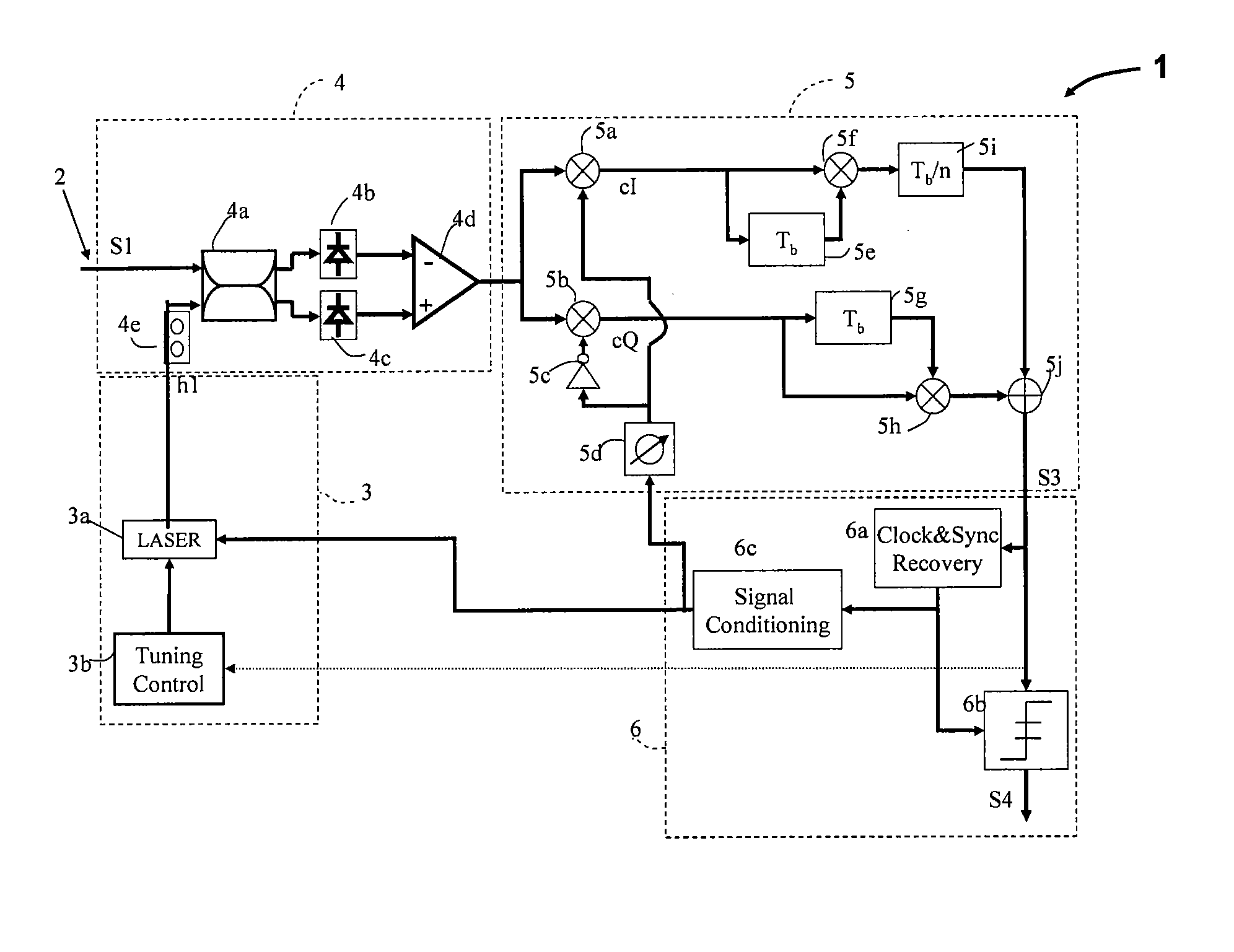
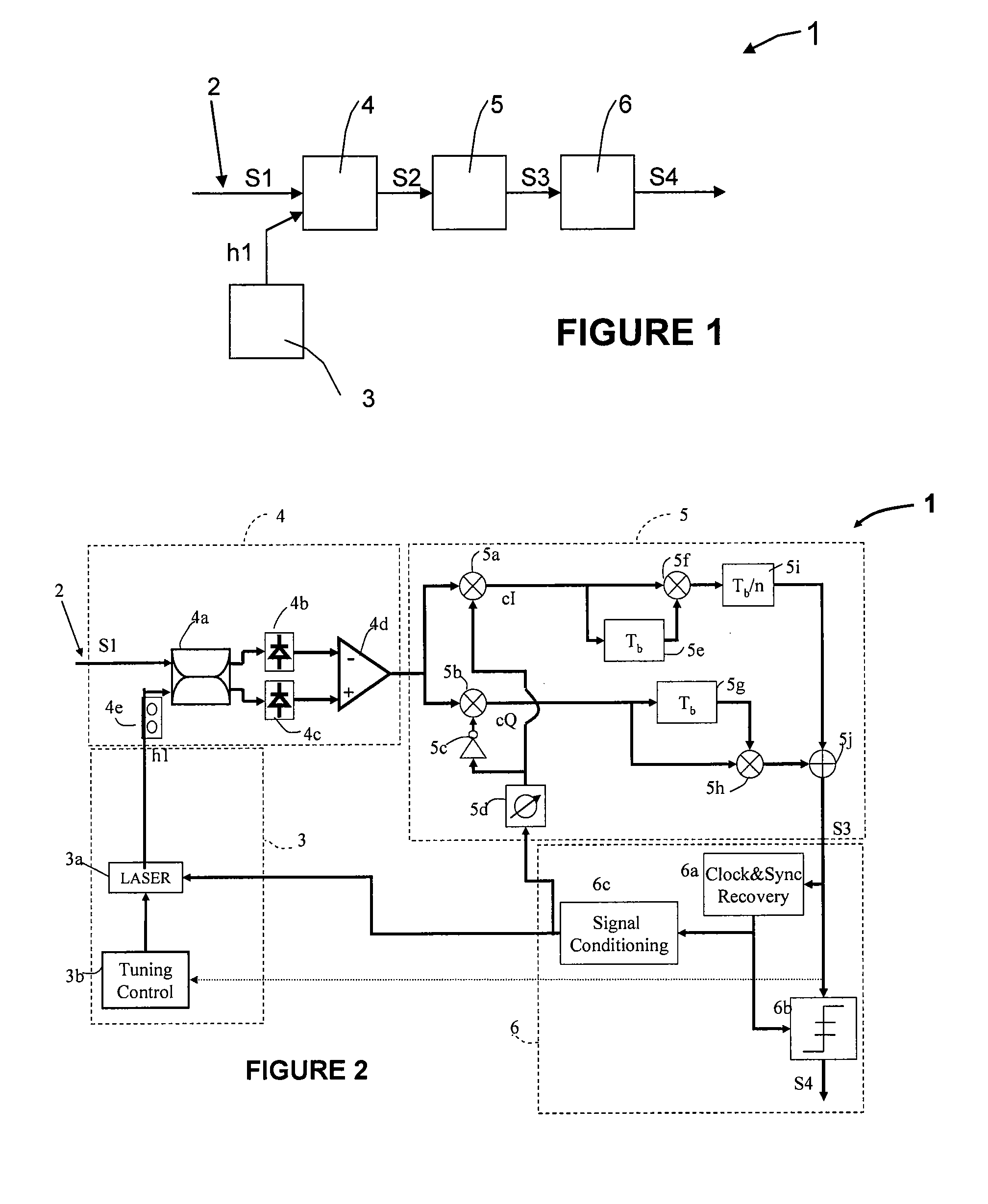
[0013]The aim of the present invention is to solve the problems above mentioned, in order to make the system more robust and cheap. One of the key features of the invention is the electric post-processing that performs differential demodulation in phase diversity, using the in-phase and quadrature components, that were previously split and are properly combined later again. With this technique, the optical channel tuning does not require a phase matching between the two lasers, and that tuning can be performed by a local laser oscillator and electrical filtering in baseband channel. By this homodyning technique, substantial improvements are achieved in the performance of the optical transmission, such as sensitivity and frequency selectivity of the invented receiver. None of the proposals published earlier, some mentioned before, use this homodyne detection system with differential demodulation; that is not strictly synchronous, but includes its advantages and reduces its requiremen...


PUM


Abstract

The receiver comprises a first optical fibre input element (2) through which an information carrying element (S1) circulates, a local laser unit (3), an optical detection unit (4) and a differential demodulation unit (5). Characterised in that the information carrying signal (S1) of the input optical fibre (2) and the light beam (h1) generated by the local laser unit (3) are connected and detect in an optical detection block (4), which converts the information carrying signal (S1) into an electrical information carrying signal (S2) to be processed electrically in a demodulation unit (5) which performs a differential demodulation of the phase and quadrature components thereof, and subsequently combines same. The result in an optical receiver (1) with homodyne optical detection, the wavelengths of the input signal S1 and the synthonised light beam h1 coinciding, with high tolerance to the phase noise generated by optical communications lasers and not requiring use of an optical phase monitor (OPLL).

Description

FIELD OF INVENTION[0001]This invention relates to optical signal transmission through a fiber optic cable. Specifically, the present invention relates to a system and a method for detection of coherent optical signals using signal processing to recover signals.BACKGROUND OF THE RELATED ART[0002]The use of fiber optic cables for the transmission of information was introduced years ago. Recently, with the growing demand for transmission of large amounts of information at high speed, the usefulness of such transmission of optical signals becomes evident. (G P Agrawal “Fiber Optic Communication Systems” John Wiley & Sons, 2002). The transmission of this information typically is done by means of binary digits (logical ones and zeros). But also analog signals are allowed, such as cable television signals.[0003]In the 90's, Wavelength Division Multiplexing (WDM) was introduced at a commercial level. This is a technique that made possible to transmit multiple wavelengths in parallel; and, t...

Claims


Application Information

Patent Timeline
Patent Type & Authority Applications(United States)
IPC IPC(8): H04B10/06H04B10/61H04B10/63
CPCH04B10/61H04B10/63H04B10/613
Inventor PRAT GOMA, JOSEPFABREGA SANCHEZ, JOSEP MARIA
Owner UNIV POLITECNICA DE CATALUNYA
Why Eureka
Try Eureka