Al technical title is built by PatSnap Al team. It summarizes the technical point description of the patent document.
a wellbore and pump system technology, applied in the direction of borehole/well accessories, positive displacement liquid engines, liquid fuel engines, etc., can solve the problems of ineffective or inefficient valve operation, erosive and damaging effects of suction valves and discharge valves, and add to the damage of fluids
Inactive Publication Date: 2010-04-22
NAT OILWELL VARCO LP
View PDF65 Cites 27 Cited by
Summary
Abstract
Description
Claims
Application Information
AI Technical Summary
This helps you quickly interpret patents by identifying the three key elements:
Problems solved by technology
Method used
Benefits of technology
[0019]Such valves with a tapered spring for facilitating effective seating of the valve member against the valve seat; and
Problems solved by technology
Both valves, the suction valve and the discharge valve, are subjected to the erosive and damaging effects of the flow of drilling fluid.
Also, mud pumps which can pump relatively hot drilling fluid at, e.g., 500 to 2000 gallons per minute, force the erosive drilling fluid against the valve parts at high velocities which add to the fluid's damaging effects.
If either surface is not flat, or if one surface does not contact the other in a substantially parallel (flat surface to flat surface) manner, ineffective or inefficient valve operation may result.
The erosive and / or damaging effects of drilling fluid flow through a valve can damage the seating surfaces so that the ideal flat-surface-to-flat surface seating is not achieved.
Also, the drilling fluid can damage a guide (e.g. ribs and a channel for receiving a stem or rod projecting from a valve member) or guide fingers so that the ideal surface seating is not achieved.
In some instances, damage to a guide or to guide fingers results in a flat valve member surface contacting a flat seating surface at an angle so that effective valve closure is not possible or so that the valve is insufficiently closed for efficient operation.
In some aspects, erosive drilling fluid flow renders initially-flat seating surfaces non-flat with resulting ineffective sealing and valve closure.
The movement of the valve member is not controlled, i.e., it is subject to a surge of fluid under pressure.
This surge of fluid can have deleterious effects on valve parts.
Method used
Image
Click on the blue label to locate the original text in one second.
Reading with bidirectional positioning of images and text.
Examples
Embodiment Construction
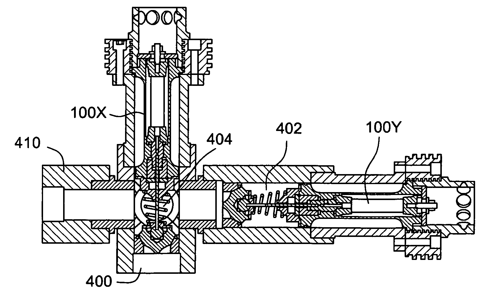
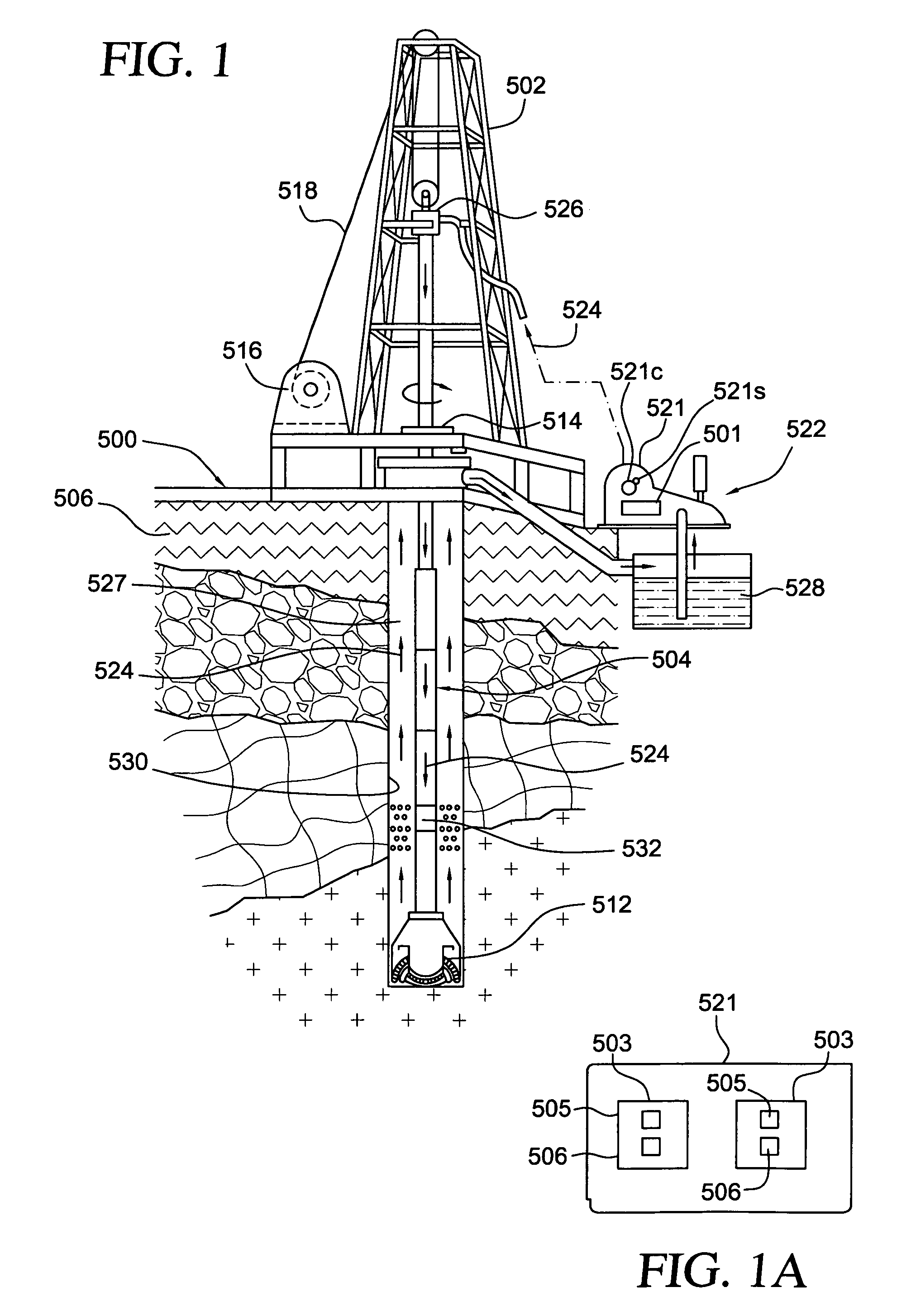
[0060]The system 500 shown in FIG. 1 includes a derrick 502 from which extends a drillstring 504 into the earth 506. The drillstring 504, as is well known, can include drill pipes and drill collars. A drill bit 512 is at the end of the drillstring. A rotary system 514, top drive system 526, and / or a downhole motor 532 (“fluid motor”, “mud motor”) may be used to rotate the drillstring 504 and the drill bit 512. A typical drawworks 516 has a cable or rope apparatus 518 for supporting items in the derrick 502. A mud pump system 522 according to the present invention with one, two, three-to-ten, or more mud pumps 521 according to the present invention each with pumping modules with one or two valves according to the present invention supplies drilling fluid 524 to the drillstring 504. Drilling forms a wellbore 530 extending down into the earth 506. Each mud pump 521 has at least one valve 501 according to the present invention or (as shown in FIG. 1A schematically) multiple pumping modu...
PUM
Abstract
A system for pumping a drilling fluid mixture, the system, in certain aspects, having a pump apparatus, the pumping apparatus having a body with an inlet and an outlet, a suction valve and a discharge valve in the body for selectively controlling flow through the body, or each valve having a curved valve seat and a valve member with a curved seating surface, the valve member selectively movable to seat against the curved valve seat to prevent the flow of the drilling fluid mixture past the valve seat; and, in one aspect, a seal in the curved valve seat against which the valve member is also sealable. This abstract is provided to comply with the rules requiring an abstract which will allow a searcher or other reader to quickly ascertain the subject matter of the technical disclosure and is submitted with the understanding that it will not be used to interpret or limit the scope or meaning of the claims, 37 C.F.R. 1.72(b).
Description
BACKGROUND OF THE INVENTION[0001]1. Field Of The Invention[0002]This present invention is directed to drilling wellbores in the earth, to systems for pumping drilling fluid (“mud”) for such operations, to mud pumping systems and valves for them, and methods of their use.[0003]2. Description of Related Art[0004]The prior art discloses a wide variety of drilling systems, apparatuses, and methods including, but not limited to, the disclosures in U.S. Pat. Nos. 6,944,547; 6,918,453; 6,802,378; 6,050,348; 5,465,799; 4,995,465; 4,854,397; and 3,658,138, all incorporated fully herein for all purposes. The prior art discloses a wide variety of drilling fluid pumps (“mud pumps”) used in drilling operations and pump systems, for example, and not by way of limitation, those pumps and systems disclosed in U.S. Pat. Nos. 6,257,354; 4,295,366; 4,527,959; 5,616,009; 4,242,057; 4,676,724; 5,823,093; 5,960,700; 5,059,101; 5,253,987; in U.S. applications Ser. No. 10 / 833,921 filed Apr. 28, 2004 (all s...
Claims
Application Information
Patent Timeline
Application Date:The date an application was filed.
Publication Date:The date a patent or application was officially published.
First Publication Date:The earliest publication date of a patent with the same application number.
Issue Date:Publication date of the patent grant document.
PCT Entry Date:The Entry date of PCT National Phase.
Estimated Expiry Date:The statutory expiry date of a patent right according to the Patent Law, and it is the longest term of protection that the patent right can achieve without the termination of the patent right due to other reasons(Term extension factor has been taken into account ).
Invalid Date:Actual expiry date is based on effective date or publication date of legal transaction data of invalid patent.
Patent Type & Authority Applications(United States)