Active electronically scanned array antenna for satellite communications

an array antenna and satellite communication technology, applied in the field of radio frequency electronics, can solve the problems of increasing the cost and complexity of the system, requiring significant amounts of time and expense for maintenance, and providing stability

Active Publication Date: 2010-04-22
RAYTHEON CO
View PDF12 Cites 51 Cited by
  • Summary
  • Abstract
  • Description
  • Claims
  • Application Information

AI Technical Summary

Problems solved by technology

When it is desired to communicate with a satellite from a vehicle that is moving, the use of mechanically steered dish antennas presents a variety of mechanical problems related to the motion of the vehicle over rough roads and uneven terrain, or during periods of high maneuverability.
Stabilization techniques are commonly used that place the antenna on a platform that is mechanically stabilized; however, these approaches often can not provide the stability required in highly dynamic maneuvers on uneven terrain, and also add cost and complexity to the system.
Mechanically steered antennas also include gimbal mechanisms, such as mechanical servos, drive motors, gears, drive belts, etc., that typically require significant amounts of time and expense for maintenance and may also break when subject to erratic movement.
In addition, conventional dish antennas are typically large and bulky, making them more visible to radar detection.
However, conventional ESA antennas, which have been used predominantly in radar applications, are typically not suitable for use in mobile satellite communications applications due to their large size, heavy weight, and high cost.
These external elements are typically large and costly, and create a single point of failure for the system in that failure of one of these elements renders the passive ESA antenna unusable.

Method used


Image

  • Active electronically scanned array antenna for satellite communications
  • Active electronically scanned array antenna for satellite communications
  • Active electronically scanned array antenna for satellite communications

Examples


Embodiment Construction

[0020]Illustrative embodiments and exemplary applications will now be described with reference to the accompanying drawings to disclose the advantageous teachings of the present invention.

[0021]While the present invention is described herein with reference to illustrative embodiments for particular applications, it should be understood that the invention is not limited thereto. Those having ordinary skill in the art and access to the teachings provided herein will recognize additional modifications, applications, and embodiments within the scope thereof and additional fields in which the present invention would be of significant utility.

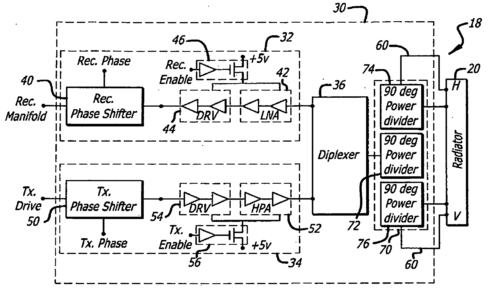
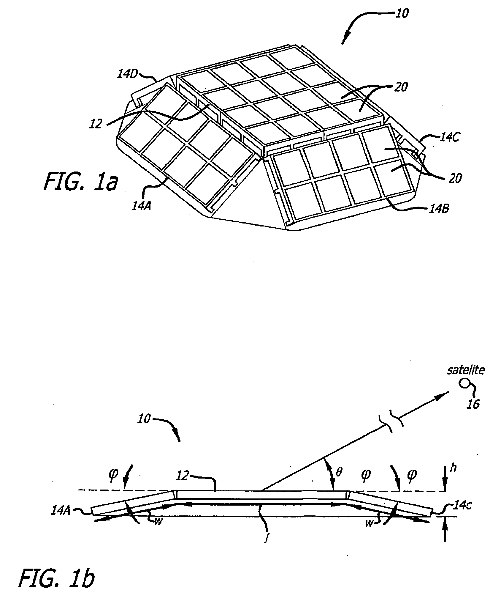
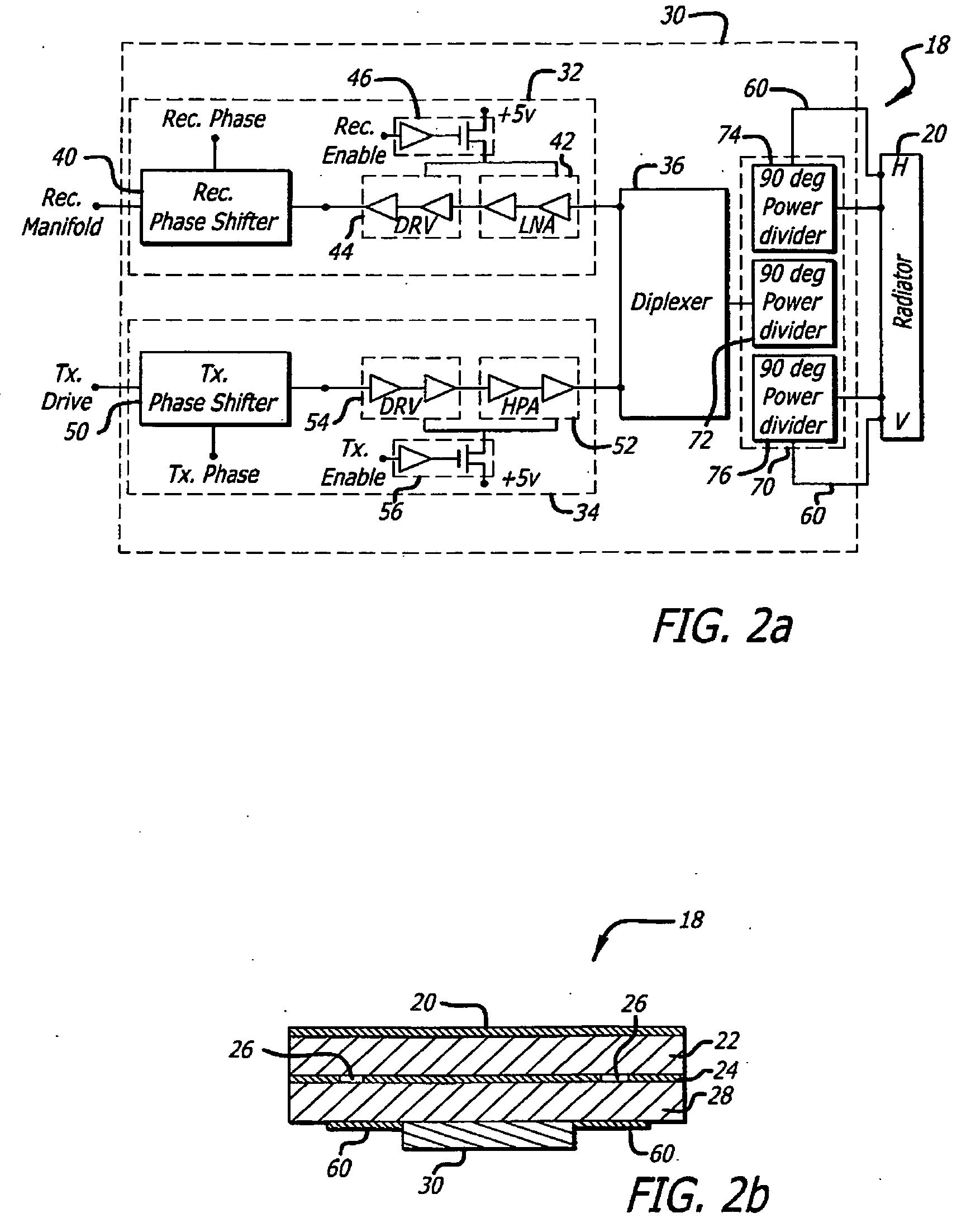
[0022]The present invention provides a novel antenna for satellite communications that uses an active electronically scanned array (ESA), or phased array. Unlike dish antennas that use mechanical servos and drive motors to steer the dish antenna to the desired angle, a phased array steers the transmit / receive beam by independently controlling the pha...


PUM


Abstract

An electronically scanned array antenna. The novel antenna includes a first planar array of antenna elements and one or more side planar arrays of antenna elements, each side array adjacent to the first array and tilted at a predetermined angle relative to the first array. In an illustrative embodiment, the antenna also includes a plurality of transmit / receive modules, each module coupled to one antenna element. Each transmit / receive module includes phase shifters for varying the relative phases of the antenna elements to form a desired overall beam pattern, and a low noise amplifier and high power amplifier for amplifying signals received and transmitted by the antenna element, respectively. In an illustrative embodiment, a processor provides individual phase and channel enable control signals for independently controlling the phase shifters and amplifiers, respectively, of each module.

Description

BACKGROUND OF THE INVENTION[0001]1. Field of the Invention[0002]The present invention relates to radio frequency electronics. More specifically, the present invention relates to electronically scanned array antennas for satellite communications.[0003]2. Description of Related Art[0004]Conventional satellite communication antennas have typically relied on mechanical steering approaches using a “dish” antenna to establish and maintain a link with a satellite. A dish antenna typically includes a parabolic reflector dish and a feed element that couples RF (radio frequency) signals between the reflector dish and a modem. The modem modulates data onto a carrier signal to provide a signal to be transmitted to the satellite by the antenna, and also demodulates a signal received from the satellite to extract encoded data.[0005]For “communications on the move” or mobile applications in which the antenna is located on a moving platform such as a ground vehicle, airplane, or ship, the antenna n...

Claims


Application Information

Patent Timeline
Patent Type & Authority Applications(United States)
IPC IPC(8): H04B1/04H01Q21/00H01Q1/50
CPCH01Q1/3275H01Q3/24H01Q3/26H01Q21/29H01Q21/065H01Q21/20H01Q21/0025
Inventor NICHOLS, RICHARD W.MASON, JAMES S.SHOWS, GILBERT M.ROPER, JOEL C.EPPICH, RAYMOND D.BURNUM, GUSTAVO A.CHANG, IKE
Owner RAYTHEON CO
Why Eureka
Try Eureka