
Video distribution system and video distribution method

a video distribution system and video technology, applied in the field of video distribution system and video distribution method, can solve the problems of not being able to guarantee the bandwidth required for distributing video content, not being able to render services that operate stably, and not being able to provide sufficient guaranteed qos, etc., to achieve the effect of reducing the amount of bandwidth used

Active Publication Date: 2010-04-22
NEC CORP
View PDF3 Cites 13 Cited by
  • Summary
  • Abstract
  • Description
  • Claims
  • Application Information

AI Technical Summary

Benefits of technology

The present invention provides a video distribution system that guarantees quality of service (QoS) on an NGN (next generation network) without significantly modifying portal servers and video distribution servers of the background art. The system includes a user terminal, a bandwidth controller, an SIP session controller, and a video distribution server interconnected through an IP network. The system allows for a flexible approach to selecting a desired bandwidth for distributing video content, ensuring stable communication services. The technical effects of the invention include improved video distribution service that guarantees QoS and stable communication services, as well as a simplified and cost-effective solution for providing video distribution on an NGN.

Problems solved by technology

Video distribution systems have been suffering problems in that they fail to provide sufficiently guaranteed QoS (Quality of Service) and, as a result, cannot guarantee a bandwidth that is required for distributing video content and do not necessarily render services that operate stably.
Patent document 2 (JP-A No. 2005-12655) has been proposed because the control between the content server and the region manager in the invention disclosed in Patent document 1 is complex and it has cost and flexibility problems that remain to be solved because general-purpose protocols are not applied.

Method used


Image

  • Video distribution system and video distribution method
  • Video distribution system and video distribution method
  • Video distribution system and video distribution method

Examples


Embodiment Construction

[0049]A first exemplary embodiment of the present invention will be described below with reference to the drawings.

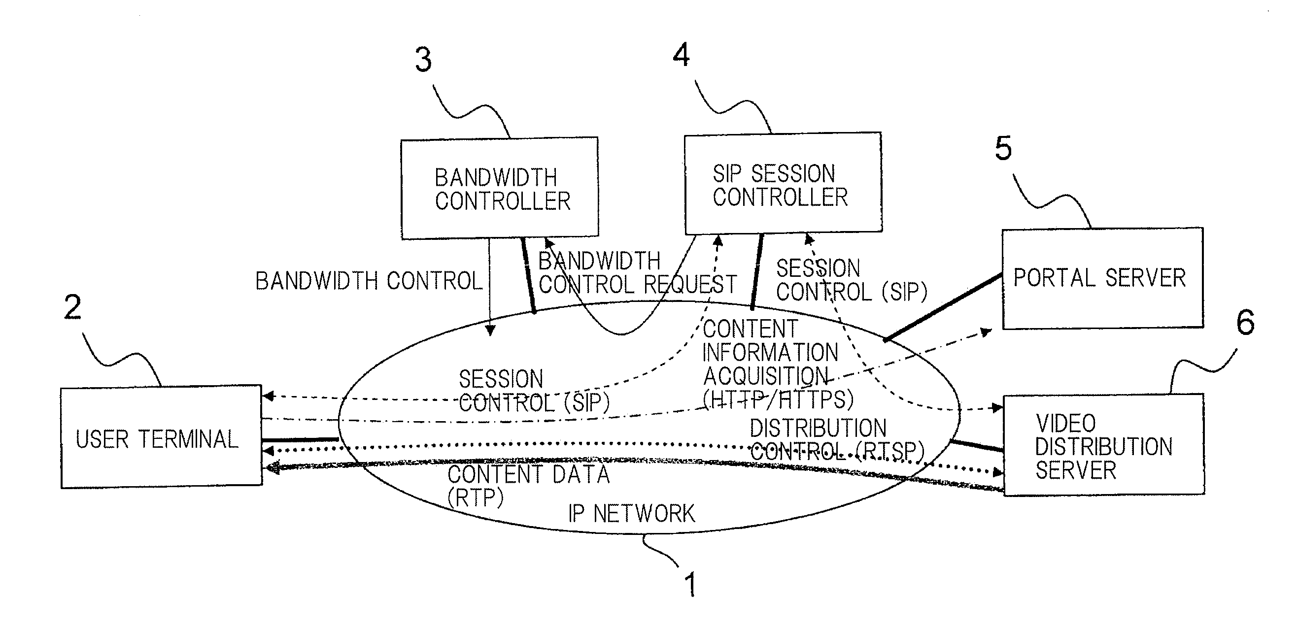
[0050]FIG. 1 is a block diagram of a configuration according to the first exemplary embodiment of the present invention. As shown in FIG. 1, the present exemplary embodiment comprises IP network 1 which is an NGN, user terminal 2, bandwidth controller 3, SIP session controller 4, portable server 5, and video distribution server 6. User terminal 2, bandwidth controller 3, SIP session controller 4, portable server 5, and video distribution server 6 are interconnected through IP network 1.

[0051]Each of user terminal 2, bandwidth controller 3, SIP session controller 4, portable server 5, and video distribution server 6 includes a CPU, a main memory, an output device, an input device, an external storage, etc., and is assumed to be of a computer configuration for installing programs and data stored in a recording medium such as a CD-ROM or the like into external storage thro...


PUM


Abstract

A video distribution system according to the present invention includes a user terminal, an SIP session controller, and a video distribution server. When the SIP session controller receives a request to establish a session, the SIP session controller establishes a session between the user terminal and the video distribution server, and controls a bandwidth controller to reserve a bandwidth for the distribution of video content in a communication path between the user terminal and the video distribution server. The video distribution server sends a bandwidth changing request for requesting the SIP session controller to change the bandwidth to reserve a bandwidth depending on a fraction of the bandwidth that is needed for distributing video content. In response to the bandwidth changing request, the SIP session controller further secures a bandwidth for the distribution of video content in the communication path between the user terminal and the video distribution server.

Description

TECHNICAL FIELD[0001]The present invention relates to a system for and a method of distributing video using an IP (Internet Protocol) network.BACKGROUND ART[0002]Video distribution systems have been suffering problems in that they fail to provide sufficiently guaranteed QoS (Quality of Service) and, as a result, cannot guarantee a bandwidth that is required for distributing video content and do not necessarily render services that operate stably.[0003]The invention disclosed in Patent document 1 (JP-A No. 2003-051846) is directed to a technology for obtaining a bandwidth required for video distribution. Patent document 1 reveals a system wherein when a content request is received from a user terminal, a content server sends a bandwidth reservation request to a region manager, and, if the region manager is able to accept the bandwidth reservation request, the region manager sends a bandwidth reservation setting request to a bandwidth controller.[0004]Patent document 2 (JP-A No. 2005-...

Claims


Application Information

Patent Timeline
Patent Type & Authority Applications(United States)
IPC IPC(8): H04N7/173H04L47/765H04N21/2385H04N21/643
CPCH04L65/1006H04L65/80H04L65/4069H04L65/61H04L65/1104
Inventor SUGIYAMA, KAORIOCHIAI, KATSUHIRO
Owner NEC CORP
Learn More