Device For Introducing A Liquid Into A Gas Flow

Active Publication Date: 2010-04-29
PUREM GMBH
View PDF10 Cites 26 Cited by
  • Summary
  • Abstract
  • Description
  • Claims
  • Application Information

AI Technical Summary

Benefits of technology

[0006]The present invention deals with the problem of stating an improved or at least another embodiment for a device of the type

Problems solved by technology

Through the provision of a convex contour sharp-edged trans

Method used


Image

  • Device For Introducing A Liquid Into A Gas Flow
  • Device For Introducing A Liquid Into A Gas Flow
  • Device For Introducing A Liquid Into A Gas Flow

Examples


Embodiment Construction

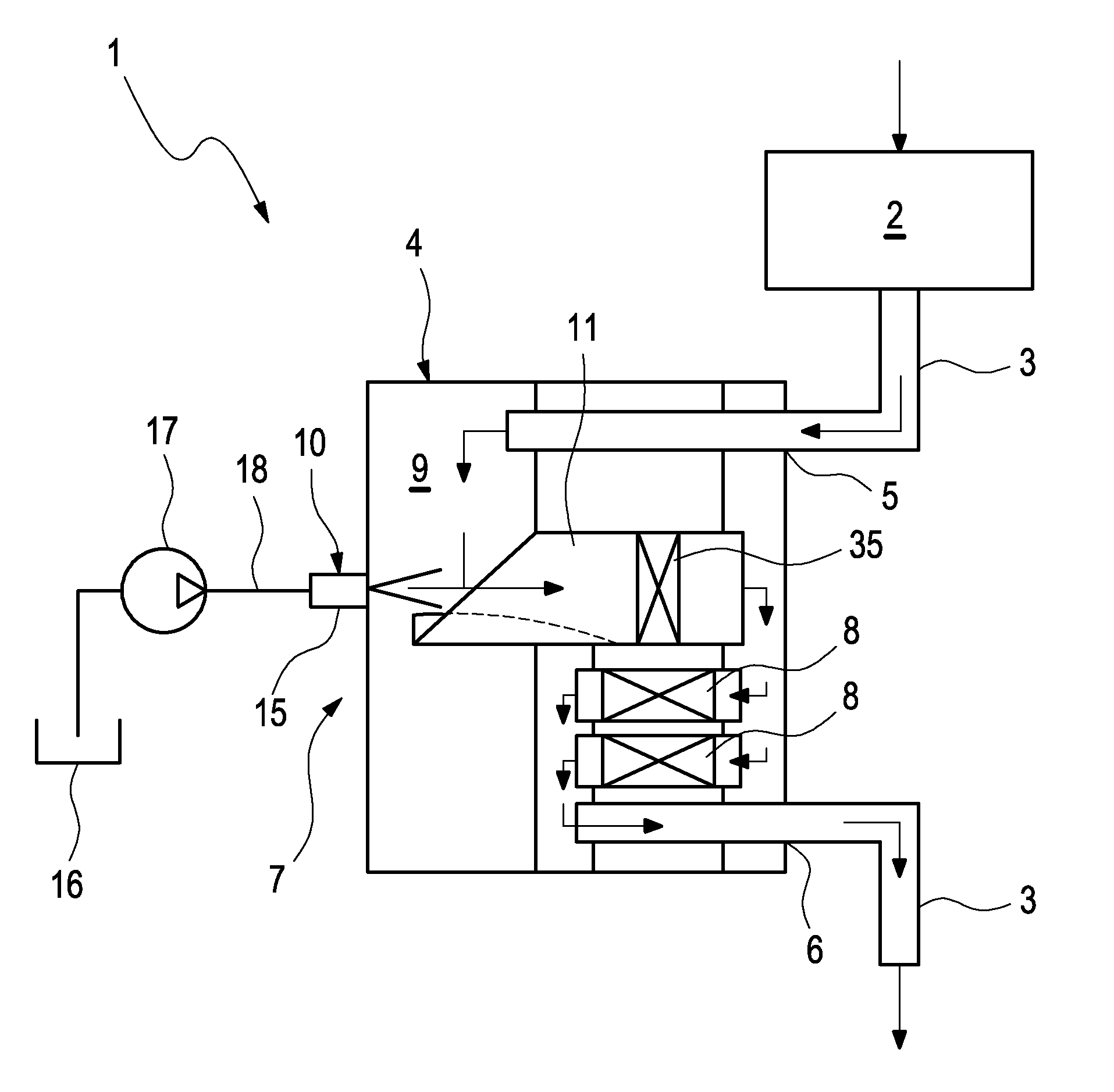
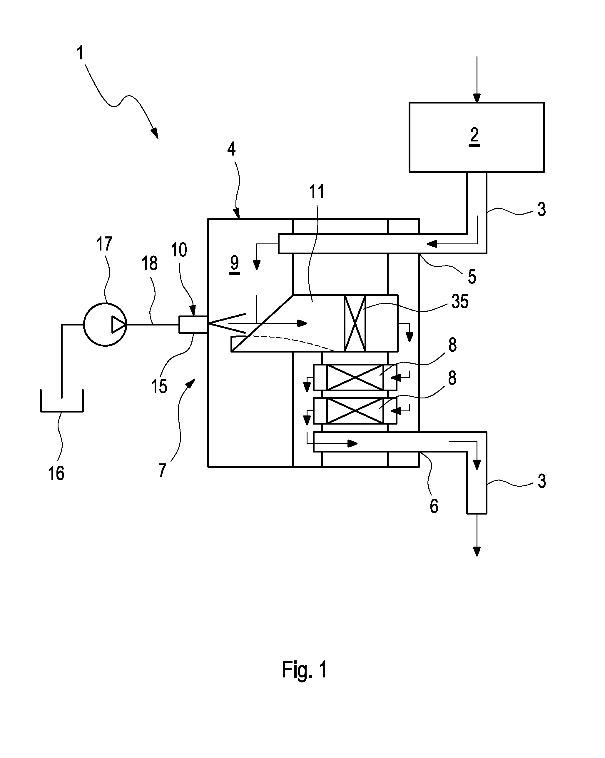
[0017]According to FIG. 1, an exhaust system 1, with the help of which exhaust gas is to be discharged from an internal combustion engine 2, comprises at least 1 exhaust line 3 to which at least one exhaust gas treatment device 4 is connected. In the example, the exhaust line 3 comprises a section leading from the internal combustion engine 2 to an inlet 5 of the exhaust gas treatment device 4 as well as a section leading away from an outlet 6 of the exhaust gas treatment device 4. It is clear that a configuration of this type is to be understood purely exemplarily and without restriction of the generality. The internal combust engine 2, preferably together with the exhaust system 1, can be present in a motor vehicle.

[0018]A device 7 with the help of which a liquid can be introduced into a gas flow, here into an exhaust gas flow, is integrated in the exhaust gas treatment device 4. For example, a watery urea solution is introduced into the exhaust gas flow with the help of this devi...


PUM


Abstract

The present invention relates to a device for introducing a liquid into a gas flow, more preferably for an exhaust system of an internal combustion engine. The device includes a chamber, an injection device and a channel. The channel with a circumferential region of an inlet section protrudes into the chamber and there on an inner side facing the gas flow has a surface. Said surface is arranged offset to the inside with respect to a channel profile. The proposed design results in improved evaporation of the liquid introduced into the gas flow.

Description

CROSS-REFERENCE TO RELATED PATENT APPLICATIONS[0001]This patent application claims the benefit of co-pending German Patent Application No. DE 102008053168.5, filed Oct. 24, 2008, the entire teachings and disclosure of which are incorporated herein by reference thereto.FIELD OF THE INVENTION[0002]The present invention relates to a device for introducing a liquid into a gas flow, more preferably for an exhaust system of an internal combustion engineBACKGROUND OF THE INVENTION[0003]With exhaust systems, it is known to introduce different liquid educts into the gas flow in order to trigger different reactions. For example, liquid fuel can be injected upstream of an oxidation catalytic converter in order to bring about heating-up of the exhaust gas flow through a subsequent, exothermal reaction in the catalytic converter and thereby indirectly heating-up of downstream exhaust gas treatment devices. For example, a particle filter for its regeneration can be heated up to a self-igniting te...

Claims


Application Information

Patent Timeline
IPC IPC(8): F01N3/04B05B1/26
CPCF01N3/206F01N3/2066F01N2610/02Y02T10/24F01N2610/14F01N2610/1453F01N2610/03Y02T10/12
Inventor OESTERLE, JOERGBRAUN, JOACHIM
Owner PUREM GMBH
Why Eureka
Try Eureka