
Punch for a rotary press

a rotary press and punch technology, applied in the direction of presses, shaping presses, perforating tools, etc., can solve the problems of high wear, inability to replace the punch inserts within the rotary press, and troublesome fastening of the punch inserts, so as to achieve good washability of the entire punch

Active Publication Date: 2010-04-29
FETTE
View PDF6 Cites 2 Cited by
  • Summary
  • Abstract
  • Description
  • Claims
  • Application Information

AI Technical Summary

Benefits of technology

"The present invention relates to a compression punch for use in a rotary press. The punch has a smooth surface and is easy to install and disassemble. It is connected to the punch shaft through a tensioning head and a drawbar, which can be easily adjusted to pull the punch insert against the punch shaft. The connection between the punch insert and the punch shaft is secure and prevents rotation. The close fit of the punch insert on the punch shaft takes place through even surfaces or a position pin. The invention allows for good washability of the punch and significant savings in production costs."

Problems solved by technology

Installation and disassembly of the punch inserts is sumptuous, and time-consuming in particular.
Replacement of the punch inserts is not possible within the rotary press.
The fastening of the punch inserts is susceptible to troubles and subject to high wear.
Problems arise also with respect to the centring and alignment of the punch inserts, with compression moulds that are not round in particular.
Finally, even the aptitude for cleaning of the known compression punches is bad, in particular if they must remain in the press (CIP=Cleaning in Place).

Method used


Image

  • Punch for a rotary press
  • Punch for a rotary press
  • Punch for a rotary press

Examples


Embodiment Construction

[0017]While this invention may be embodied in many different forms, there are described in detail herein a specific preferred embodiment of the invention. This description is an exemplification of the principles of the invention and is not intended to limit the invention to the particular embodiment illustrated

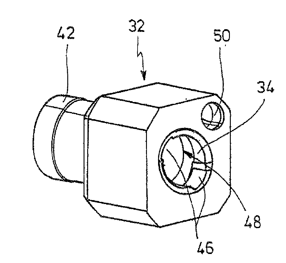
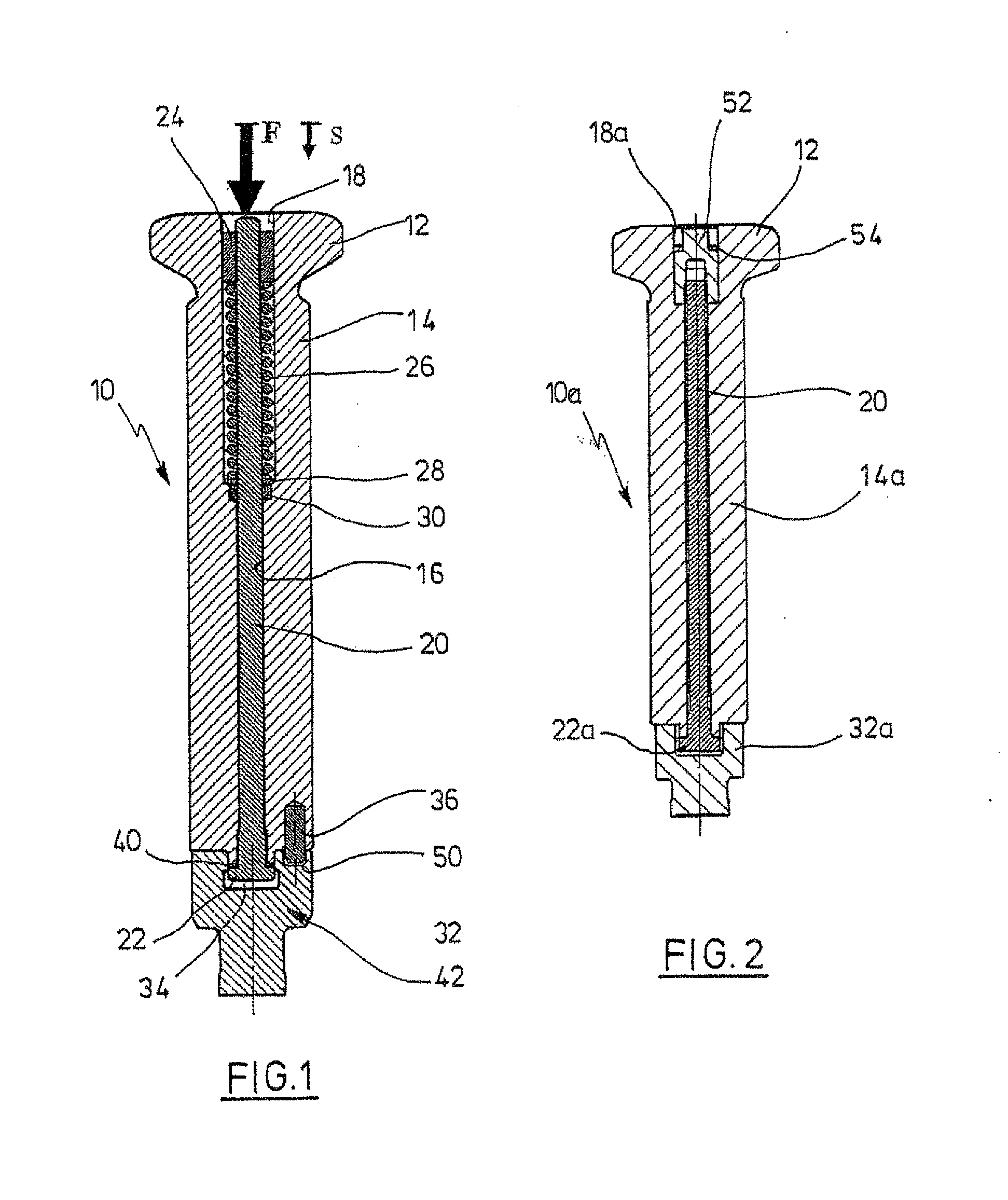
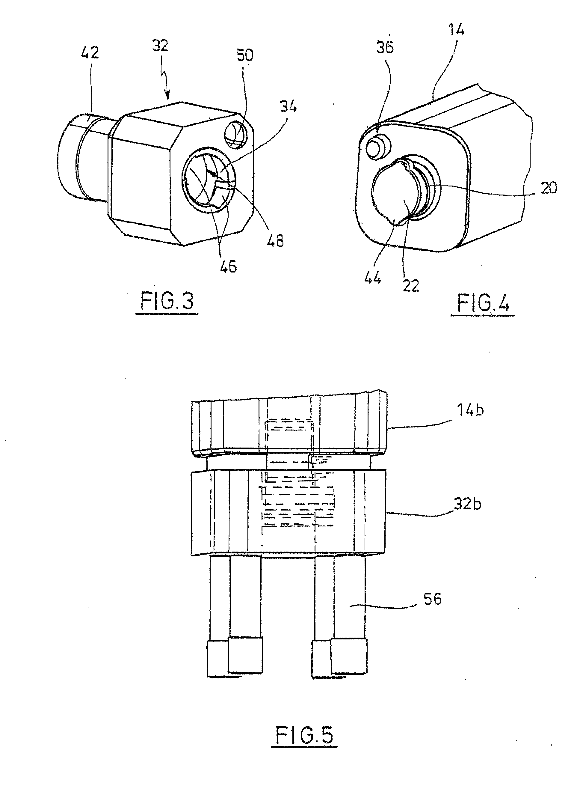
[0018]A compression punch 10 with a punch head 12 and a punch shaft 14 is shown in FIG. 1. Punch head 12 and punch shaft 14 have a radial through bore 16. On the end facing the punch head 12, the through bore 16 has a bore portion 18 with a greater diameter. The through bore 16 accommodates a drawbar 20, which has a tensioning head 22 on its lower end. On the upper end, the drawbar 20 is provided with a thread, onto which a nut 24 is screwed up. The nut 24 serves as abutment for a helical spring 26 that is supported on a disk 28. The disk 28 is supported on the facing shoulder of the bore portion 18. An elastomer seal 30 is arranged below the disk 28. It has the purpose to pre...


PUM

PropertyMeasurementUnit
diameteraaaaaaaaaa
timeaaaaaaaaaa
tensile stressaaaaaaaaaa

Abstract

A compression punch for a rotary press, with a punch shaft that has a punch head at its one end and means for accommodating a separate punch insert at the other end, and with fastening means for detachably fastening the punch insert on the punch shaft, wherein the punch head and the punch shaft have an axial through bore, the axial through bore accommodates a drawbar that has a tensioning head at the end turned away from the punch head, said tensioning head having at least one connection portion, the punch insert has a recess at the end facing the punch shaft which is realised to be detachably connectible with the connection portion, and that tensioning means are arranged in the axial through bore, by which the drawbar can be tensioned in the direction of the punch head.

Description

CROSS-REFERENCE TO RELATED APPLICATIONS[0001]Not applicable.STATEMENT REGARDING FEDERALLY SPONSORED RESEARCH[0002]Not applicable.BACKGROUND OF THE INVENTION[0003]As is well known, a rotary press contains a plurality of upper and lower punches, which are guided in suitable guide bores of punch guidings and which co-operate with bores in a die plate. The individual punches feature a shaft, as well as a head at one end, which co-operates with compression rollers of the press. At the end turned away from the punch head is arranged a punch insert, which is realised separately and adapted to be connected with the shaft via suitable fastening means. The connection takes place with the aid of screws or pins. However, it is also known to realise compression punches in one single piece.[0004]The known punch constructions have several disadvantages. Installation and disassembly of the punch inserts is sumptuous, and time-consuming in particular. Replacement of the punch inserts is not possible...

Claims


Application Information

Patent Timeline
Patent Type & Authority Applications(United States)
IPC IPC(8): B26D7/26
CPCB30B11/08B30B15/065B30B15/026Y10T83/9423Y10T83/9457Y10T83/9476
Inventor MALICK, DANIELMEISSNER, FRIEDRICH
Owner FETTE
Learn More