Check patentability & draft patents in minutes with Patsnap Eureka AI!

Dll circuit and control method thereof

Inactive Publication Date: 2010-04-29
LONGITUDE LICENSING LTD
View PDF10 Cites 1 Cited by
  • Summary
  • Abstract
  • Description
  • Claims
  • Application Information

AI Technical Summary

Benefits of technology

[0013]According to the present invention, the delay amount is controlled by a second phase comparison in order to shorten the lock time, and thus the configuration becomes simple and suppression of an increase in circuit size can be achieved.

Problems solved by technology

Accordingly, operations therefore are complicated, and there is a possibility that its circuit size increases.

Method used


Image

  • Dll circuit and control method thereof
  • Dll circuit and control method thereof
  • Dll circuit and control method thereof

Examples


Embodiment Construction

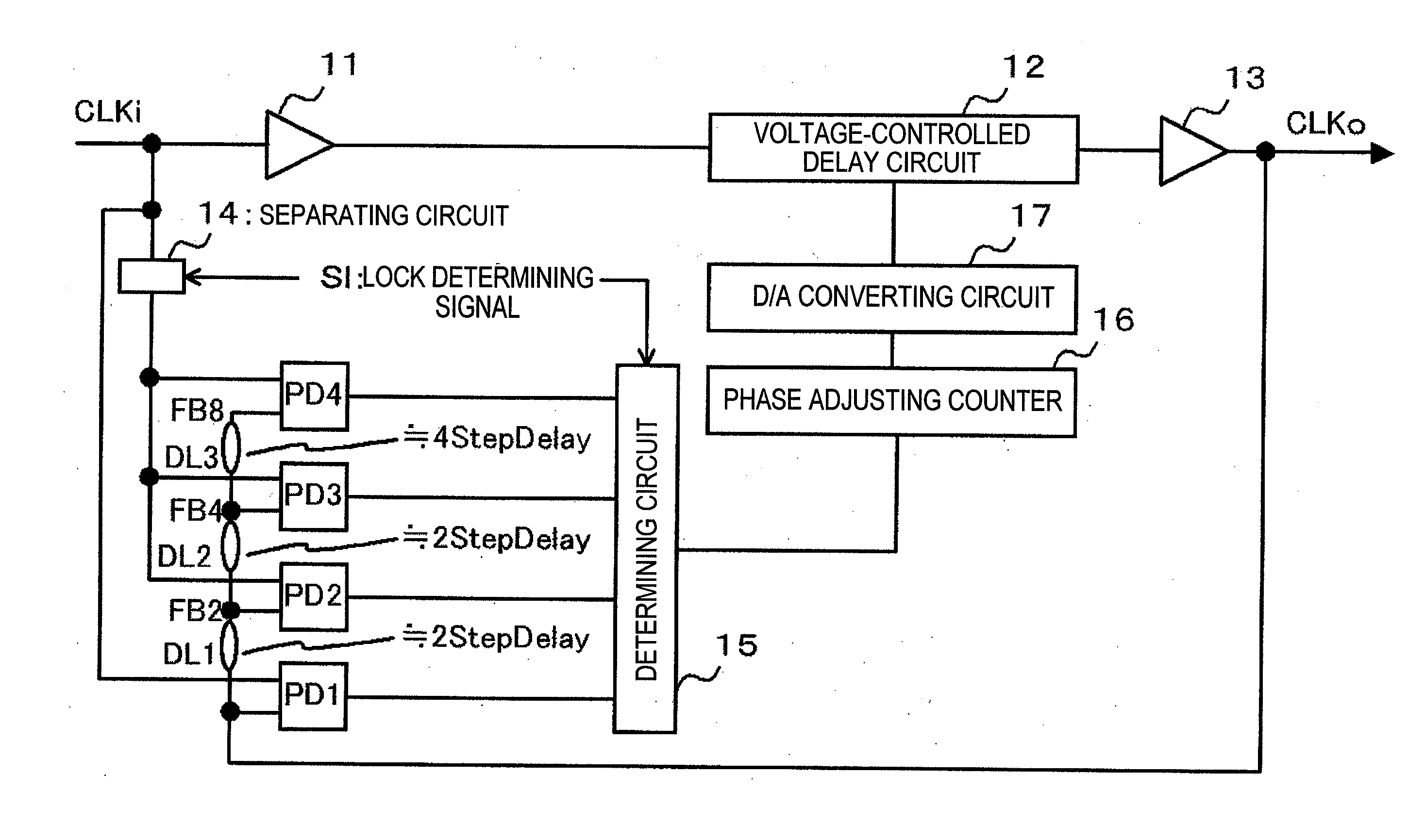
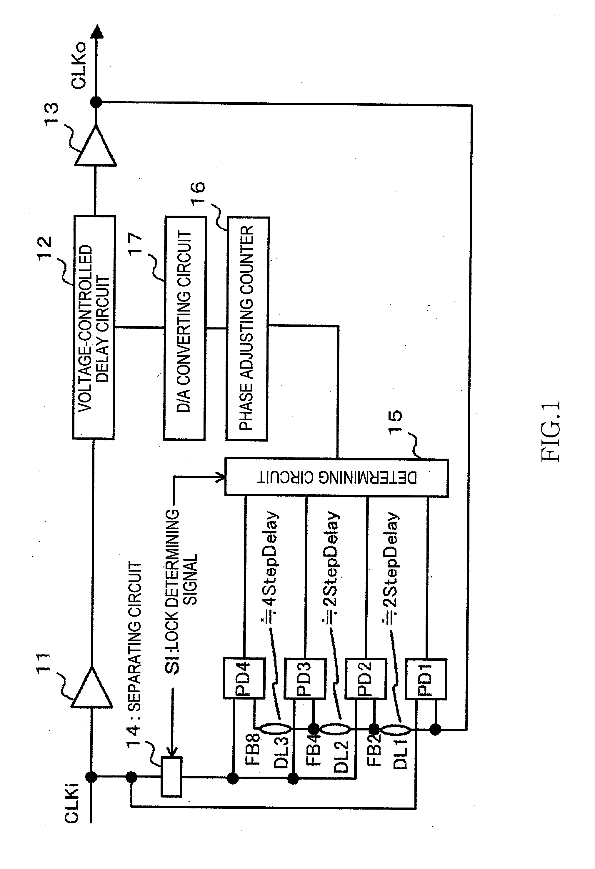
[0017]A DLL circuit according to an embodiment of the present invention outputs an input clock signal (CLKi in FIG. 1) as an output clock signal (CLKo in FIG. 1) via a variable delay circuit (reference numeral 12 in FIG. 1), and also, controls a delay amount in the variable delay circuit based on a phase comparison result between the input clock signal and output clock signal. The DLL circuit includes: a first phase comparing circuit (PD1 in FIG. 1) that compares the phases between the input clock signal and the output clock signal; a first delay circuit (DL1 in FIG. 1) that delays the output clock signal; and a second phase comparing circuit (PD2 in FIG. 1) that compares the phases between the input clock signal and an output signal of the first delay circuit. The DLL circuit is configured such that the delay amount in the variable delay circuit is controlled based on a comparison result of the first phase comparing circuit and a comparison result of the second phase comparing circ...


PUM


Abstract

A DLL circuit includes a first phase comparing circuit that compares phases between an input clock signal and an output clock signal, a first delay circuit that delays the output clock signal, and a second phase comparing circuit that compares phases between the input clock signal and an output signal of the first delay circuit. A delay amount in the variable delay circuit is controlled based on a comparison result of the first phase comparing circuit and a comparison result of the second phase comparing circuit.

Description

BACKGROUND OF THE INVENTION[0001]1. Field of the Invention[0002]The present invention relates to a DLL (Delay Locked Loop) circuit and a control method thereof, and, more particularly relates to a technique of controlling a lock time in a DLL circuit.[0003]2. Description of Related Art[0004]A DLL circuit compares phases between a received clock signal CLKi (reference clock) and a signal obtained by feeding back a clock signal CLKo output by a variable delay circuit (such as a voltage-controlled delay line) using a phase comparing circuit (PD), and reflects a comparison result on a delay time of the variable delay circuit. The DLL circuit performs control to advance or delay the phase of the clock signal CLKo, and finally operates such that the phases between the clock signal CLKo and the clock signal CLKi match (lock) each other.[0005]In a conventional DLL circuit, a delay pitch of the variable delay circuit is constant. Thus, a lock time of the DLL circuit is calculated as: (“initi...

Claims


Application Information

Patent Timeline
IPC IPC(8): H03L7/06
CPCH03L7/087H03L7/0812H03L7/0816
Inventor TAKAHASHI, HIROKIISHIKAWA, TORU
Owner LONGITUDE LICENSING LTD
Features
  • R&D
  • Intellectual Property
  • Life Sciences
  • Materials
  • Tech Scout
  • Unparalleled Data Quality
  • Higher Quality Content
  • 60% Fewer Hallucinations
Learn More