Method and Apparatus for Determining the Location of a Mobile Object

a mobile object and computer-aided technology, applied in direction finders using radio waves, transmission monitoring, instruments, etc., can solve the problems of labor- and cost-intensive calibration, significantly lower accuracy, and high cost, and achieve low cost, simple localization, and high accuracy

Inactive Publication Date: 2010-04-29
UNIFY GMBH & CO KG
View PDF13 Cites 33 Cited by
  • Summary
  • Abstract
  • Description
  • Claims
  • Application Information

AI Technical Summary

Benefits of technology

[0006]The object of the invention is to create a simple localization method which has high accuracy and can be installed with little outlay and without carrying out a multiplicity of reference measurements.
[0011]The reference map that is predetermined during initialization of the method can, for example, be computed by means of a wave propagation model. As the wave propagation model, a radial propagation model, an MWM propagation model (MWM=Multi Wall Model) or a DPM propagation model (DPM=Dominant Path Model) can, for example, be used. These propagation models will be explained in greater detail in the detailed description. Through the use of such wave propagation models, a reference map can be predetermined easily and rapidly during initialization of the method without time-consuming reference measurements having to be carried out at a multiplicity of positions. It suffices in particular for the parameters of the propagation model to be determined by a simple self-measurement by the base stations.
[0033]In a particularly preferred variant of the supervised learning method, the mobile object executes a sequence of predetermined path sections, the order of the path sections executed being suitably determined with the aid of a cost function. The cost function here preferably indicates for a respective path section how great the maximum distance of an object position on the path section is from the nearest base station or from a nearest object position which has already been traversed. By means of such a cost function, it is achieved that a large area of object positions is covered by the method as rapidly as possible.

Problems solved by technology

This calibration is labor- and cost-intensive, and the greater the accuracy desired, the more time-consuming it is.
However, these methods have the disadvantage that the accuracy they achieve is significantly lower than in methods in which a reference map is created by means of a multiplicity of measurements.

Method used


Image

  • Method and Apparatus for Determining the Location of a Mobile Object
  • Method and Apparatus for Determining the Location of a Mobile Object
  • Method and Apparatus for Determining the Location of a Mobile Object

Examples


Embodiment Construction

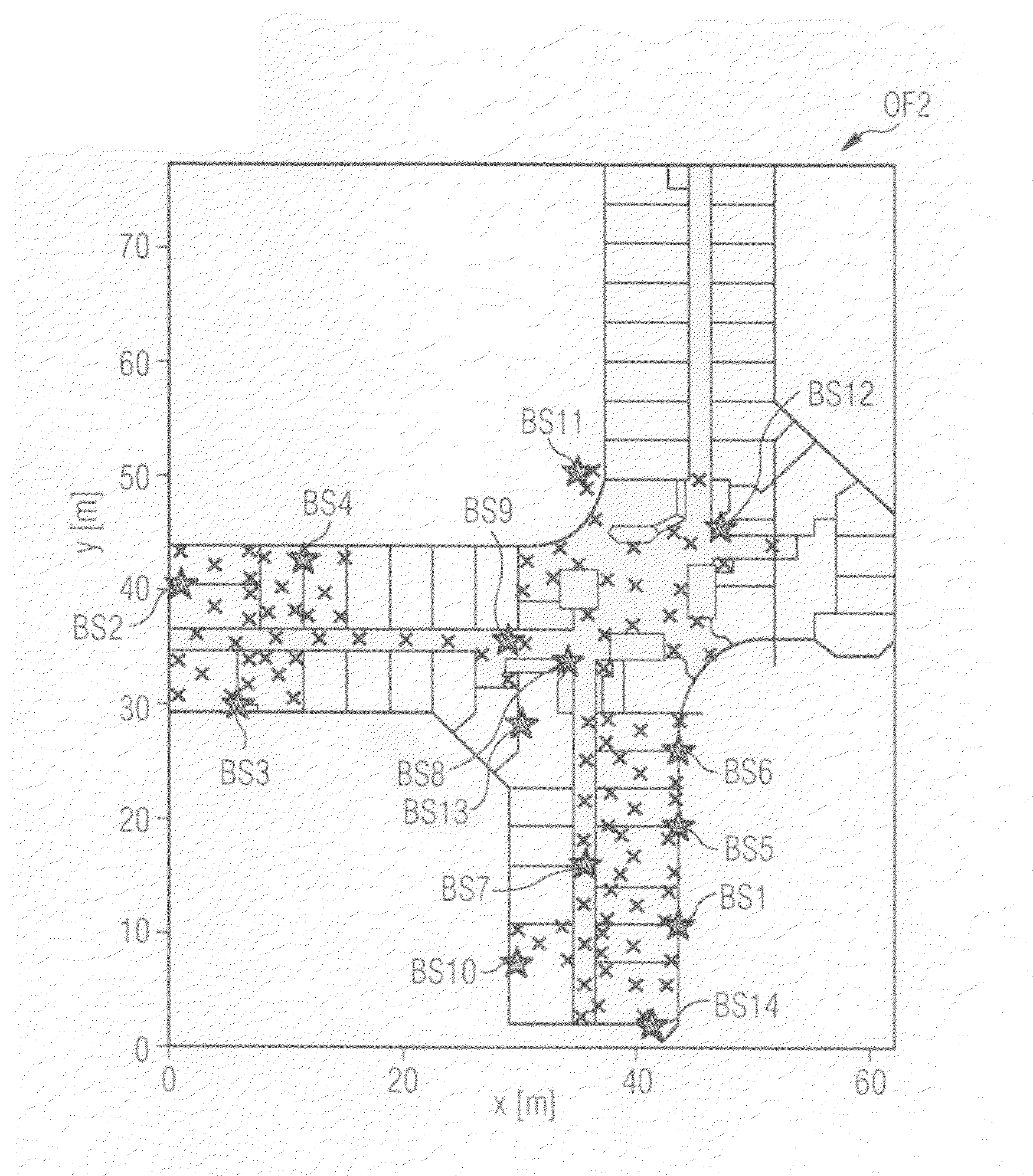
[0043]In the embodiments of the inventive method described below, a mobile object is considered which has at least one antenna, by means of which the field strengths of a plurality of base stations in the area surrounding the object can be received and measured. Here, each base station transmits wireless signals with a certain power (i.e. with a certain field-strength value). These wirelessly transmitted signals propagate in space, where they are reflected, bent and absorbed, notably by persons and other objects in the space, such as e.g. walls, machinery or office furniture, in the surrounding area.

[0044]In the exemplary embodiments of the inventive method described here, the propagation profile for each base station is described in the form of a two-or three-dimensional map, each position in the map being uniquely linked to a received field-strength value for each base station. The received field-strength value is also referred to below as the RSS value (RSS=received signal streng...


PUM


Abstract

The invention relates to a position-finding method for d4eterming the location of a mobile object. The features, for example received field strengths, of a plurality of base stations are measured, and the object position is located from these features, using a reference map. During an initialization process, a reference map is created which comprises a multiplicity of positions and the associated feature-dependent values. During use of the method, a plurality of position-finding processes are carried out, by means of each of which a measured feature-dependent value and from this, a located position of the object, are determined using the predetermined reference map. The predetermined reference map is in each case updated for at least some of the positions found, during which updates, the feature-dependent values are each corrected by a correction term at the support points of the reference map in a predetermined area surrounding an object position.

Description

CROSS REFERENCE TO RELATED APPLICATIONS[0001]This application is the US National Stage of International Application No. PCT / EP2006 / 069616, filed Dec. 12, 2006 and claims the benefit thereof. The International Application claims the benefits of German application No. 10 2006 044 293.8 filed Sep. 20, 2006 and European application No. 06006833.5 filed Mar. 31, 2006. All of the applications are incorporated by reference herein in their entirety.FIELD OF INVENTION[0002]The invention relates to a method and an apparatus for the computer-aided localization of a mobile object.BACKGROUND OF THE INVENTION[0003]Various feature-based methods for finding the position of mobile users or terminal devices in wireless communication networks are known from the prior art. As features, for example, the field strengths of fields through the mobile object are measured, the fields being generated and emitted in the communication network by a plurality of base stations. As communication networks, for examp...

Claims


Application Information

Patent Timeline
Patent Type & Authority Applications(United States)
IPC IPC(8): G01S3/02G06F17/11G01S5/02H04W64/00
CPCG01S5/0252H04B17/318H04B17/391H04W64/00G01S5/02524
Inventor BAMBERGER, JOACHIMPARODI, BRUNO BETONIHORN, JOACHIMLENZ, HENNINGSZABO, ANDREI
Owner UNIFY GMBH & CO KG
Why Eureka
Try Eureka