Array layout for color mixing

a color mixing and array technology, applied in lighting and heating apparatus, lighting support devices, instruments, etc., can solve the problems of heat retention, mixing difficulty, and optical loss when light is reflected

Active Publication Date: 2010-04-29
CREELED INC
View PDF110 Cites 132 Cited by
  • Summary
  • Abstract
  • Description
  • Claims
  • Application Information

AI Technical Summary

Benefits of technology

[0014]Another embodiment according to the present invention comprises a light emitting diode (LED) component having an array of LED chips comprising a first group of LED chips and one or more additional groups of LED chips. The first group of LEDs is arranged so that at least three LED chips from the one or more additional groups is adjacent each of the LED chips in the first group. A lens is included over the array.
[0015]Another embodiment according to the present invention comprises a light emitting diode (LED) component having an array of LED chips mounted on a submount. The array of LED chips comprises a first group of LED chips and one or more additional groups of LED chips. The array is arranged so that less than fifty percent (50%) of the LED chips in the first group of LED chips is on the perimeter of the array.
[0016]Another embodiment according to the present invention comprises a light emitting diode (LED) component h...

Problems solved by technology

While the reflective cup 13 may direct light in an upward direction, optical losses may occur when the light is reflected (i.e. some light may be absorbed by the reflector cup due to the less than 100% reflectivity of practical reflector surfaces).
In addition, heat retention may be an issue for a package such as the package 10 shown in FIG. 1, since it may be difficult to extract heat through the leads 15A, 15B.
There can be challenges in producing high quality light from different colors emitted by the LED packages.
Mixing can be difficult when using specular reflectors in that the reflector images the light sources.
One difficulty with mixing in the far field is that the individual discrete sources can be perceived when the lamp or luminaire is viewed directly.
However, mechanically obscuring the light sources may result in lower efficiency as light is typically lost by the mechanical shielding.
While the mixing chamber approach has resulted in very high efficacies for the LR6 lamp of approximately 60 lumens/watt, one drawback of this approach is that a minimum spacing is required between the diffuser lens (which can be a lens and diffuser film) and the light sources.
The actual spacing can...

Method used


Image

  • Array layout for color mixing
  • Array layout for color mixing
  • Array layout for color mixing

Examples


Embodiment Construction

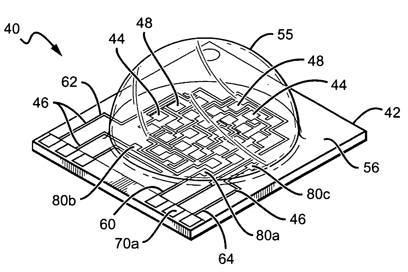
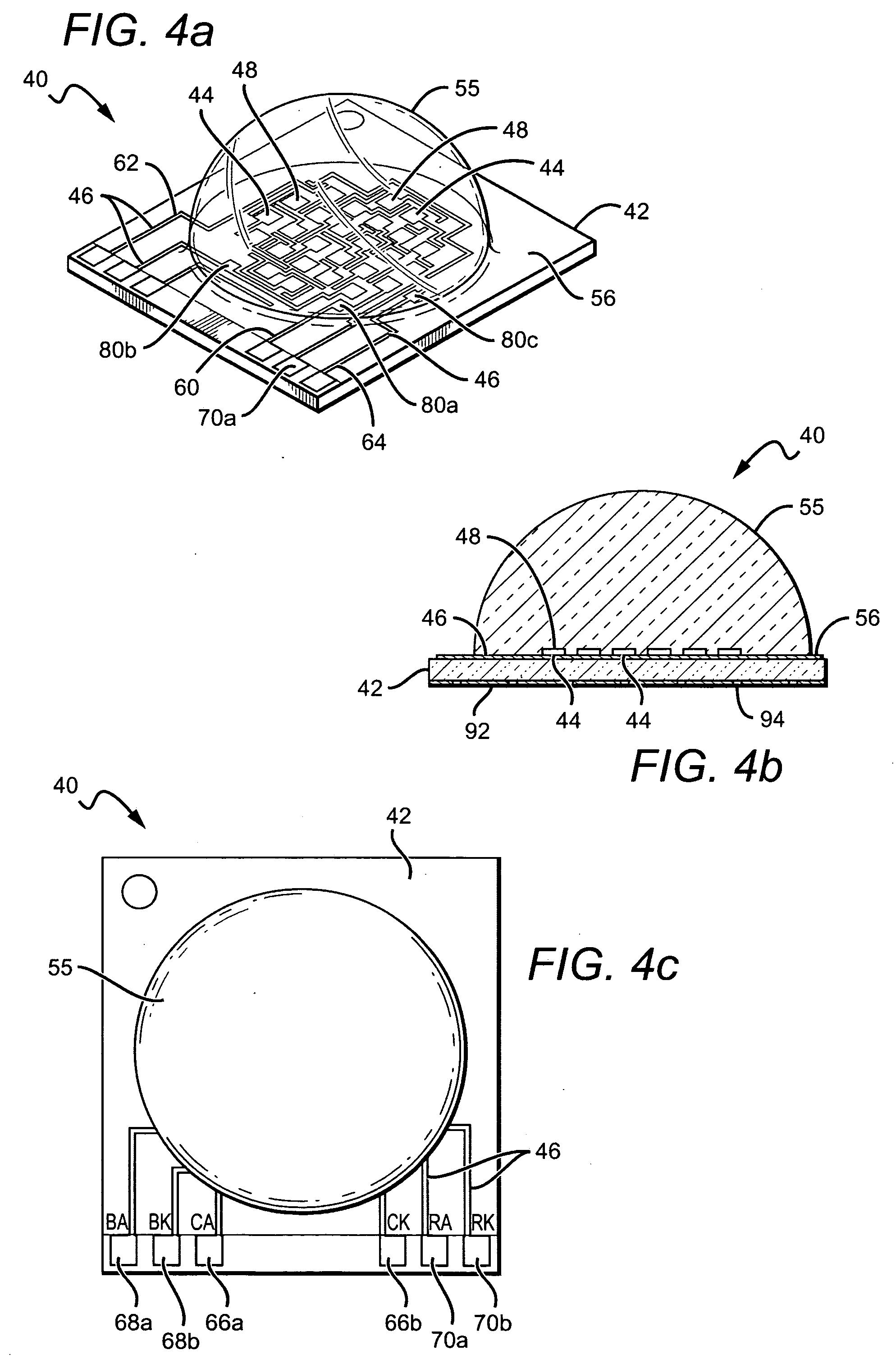
[0032]The present invention comprises a solid state lighting component, lamp or luminaire having a plurality or array of discrete light sources comprising groups of light sources emitting at different colors of light. The present invention is described with reference to the LED components utilizing LEDs or LED chips, but it is understood that lighting components according to the present invention can utilize different light sources including other solid state light sources.

[0033]LED components according to the present invention illuminate the array of LED chips to emit a color combination of light from the LED chips. In one embodiment an LED component emits a white light combination or mixture of light from its LED chips. The configuration of the particular LED chips in the array can contribute to the ability to mix in the near field and in particular for specular reflector systems, in the far field. Random placement of the LED chips in the array can reduce natural color mixing from...


PUM


Abstract

Lamps, luminaries or solid state lighting components are disclosed having multiple discrete light sources whose light combines to provide the desired emission characteristics. The discrete light sources are arranged in an array pursuant to certain guidelines to promote mixing of light from light sources emitting different colors of light. One embodiment solid state lighting component comprises a light emitting diode (LED) component having an array of LED chips having a first group of LED chips and one or more additional groups of LED chips. The array is arranged so that no two LED chips from said first group are directly next to one another in the array, that less than fifty percent (50%) of the LED chips in the first group of LEDs is on the perimeter of the array, and at least three LED chips from the one or more additional groups is adjacent each of the LED chips in the first group.

Description

BACKGROUND OF THE INVENTION[0001]1. Field of the Invention[0002]This invention relates to solid state lighting and in particular to solid state lighting utilizing a plurality of discrete emitter arranged to promote color mixing.[0003]2. Description of the Related Art[0004]Light emitting diodes (LED or LEDs) are solid state devices that convert electric energy to light, and generally comprise one or more active layers of semiconductor material sandwiched between oppositely doped layers. When a bias is applied across the doped layers, holes and electrons are injected into the active layer where they recombine to generate light. Light is emitted from the active layer and from all surfaces of the LED.[0005]In order to use an LED chip in a circuit or other like arrangement, it is known to enclose an LED chip in a package to provide environmental and / or mechanical protection, color selection, light focusing and the like. An LED package also includes electrical leads, contacts or traces fo...

Claims


Application Information

Patent Timeline
IPC IPC(8): F21V9/00F21V5/00F21V17/06F21S4/00
CPCH01L25/0753H01L25/167H01L2924/3025H01L2224/32245H01L2224/73265H01L2224/48247H01L2224/48091H01L33/58H01L2924/00014H01L2924/00H01L2924/181H01L2924/00012G02B6/0068
Inventor VAN DE VEN, ANTONY P.NEGLEY, GERALD
Owner CREELED INC
Why Eureka
Try Eureka