Low-profile elongated LED light fixture

a led light fixture, low-profile technology, applied in the direction of lighting and heating apparatus, lighting applications, domestic cooling devices, etc., can solve the problems of uneven light distribution and brightness, high material and component costs, difficult and time-consuming assembly, etc., to increase the lighting performance of the fixture and the wide range of illumination

Active Publication Date: 2010-04-29
ELECTRALED
View PDF54 Cites 69 Cited by
  • Summary
  • Abstract
  • Description
  • Claims
  • Application Information

AI Technical Summary

Benefits of technology

[0009]The present invention is directed to a lighting fixture having two groups or arrays of LED modules that are angularly positioned to each other to produce a broad range of illumination. The fixture includes an elongated housing with angled support members, a group of LEDs mounted to each support member, opposed end walls, a top post, and a multiple cover sections that couples to the housing and extends between the end walls and the top post. A circuit board is energized by a external power supply and is positioned along the length of the fixture in connection with the support members. Current flows through the circuit board using a copper trace to illuminate the LED thereon. Because the support members are angularly oriented, the two groups of LEDs are similarly angled. The angled orientation of the two LED groups increase the light distribution angle of the fixture, thereby increasing the lighting performance of the fixture. According to an aspect of the invention, the fixture includes a radio frequency control unit that allows an operator to remotely control the fixture or group of fixtures, including turning the fixtures on, off, or dimming the brightness of the fixtures.

Problems solved by technology

While such fixtures provide some beneficial features, they nevertheless suffer from a number of limitations, including but not limited to, uneven light distribution and brightness, high material and component costs, difficult and time-consuming assembly, and cumbersome housing configurations that hamper installation and thus prevent custom applications.
Because the LEDs 44 are linearly arranged in a single plane, the tube 20 produces a limited range of light that is uneven and susceptible to undesirable “hot spots.” This poor lighting performance renders the tube 20 commercially unfeasible.
These walk-in coolers are not free-standing as recognized within the industry, however, they include a number of similar components including mullions and openable doors with seals.

Method used


Image

  • Low-profile elongated LED light fixture
  • Low-profile elongated LED light fixture
  • Low-profile elongated LED light fixture

Examples


Embodiment Construction

[0021]While this invention is susceptible of embodiments in many different forms, there are shown in the drawings and will herein be described in detail preferred embodiments of the invention with the understanding that the present disclosure is to be considered as an exemplification of the principles of the invention and is not intended to limit the broad aspect of the invention to the embodiments illustrated.

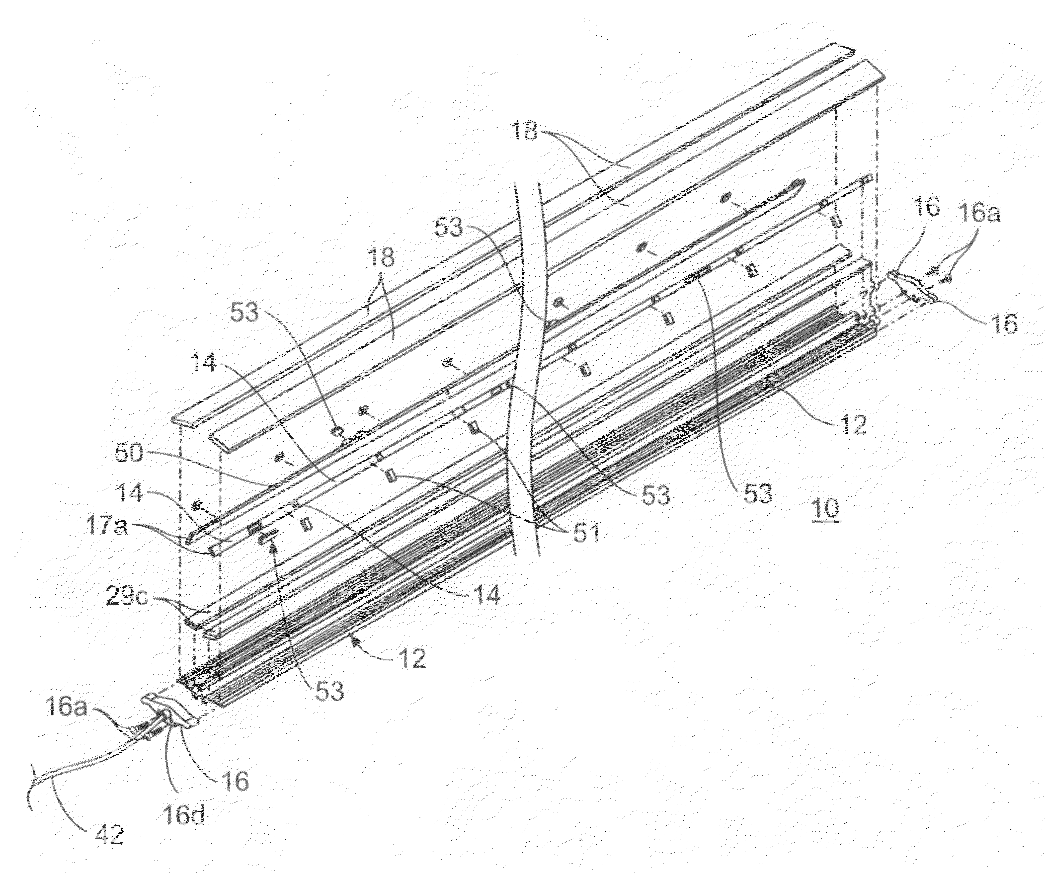
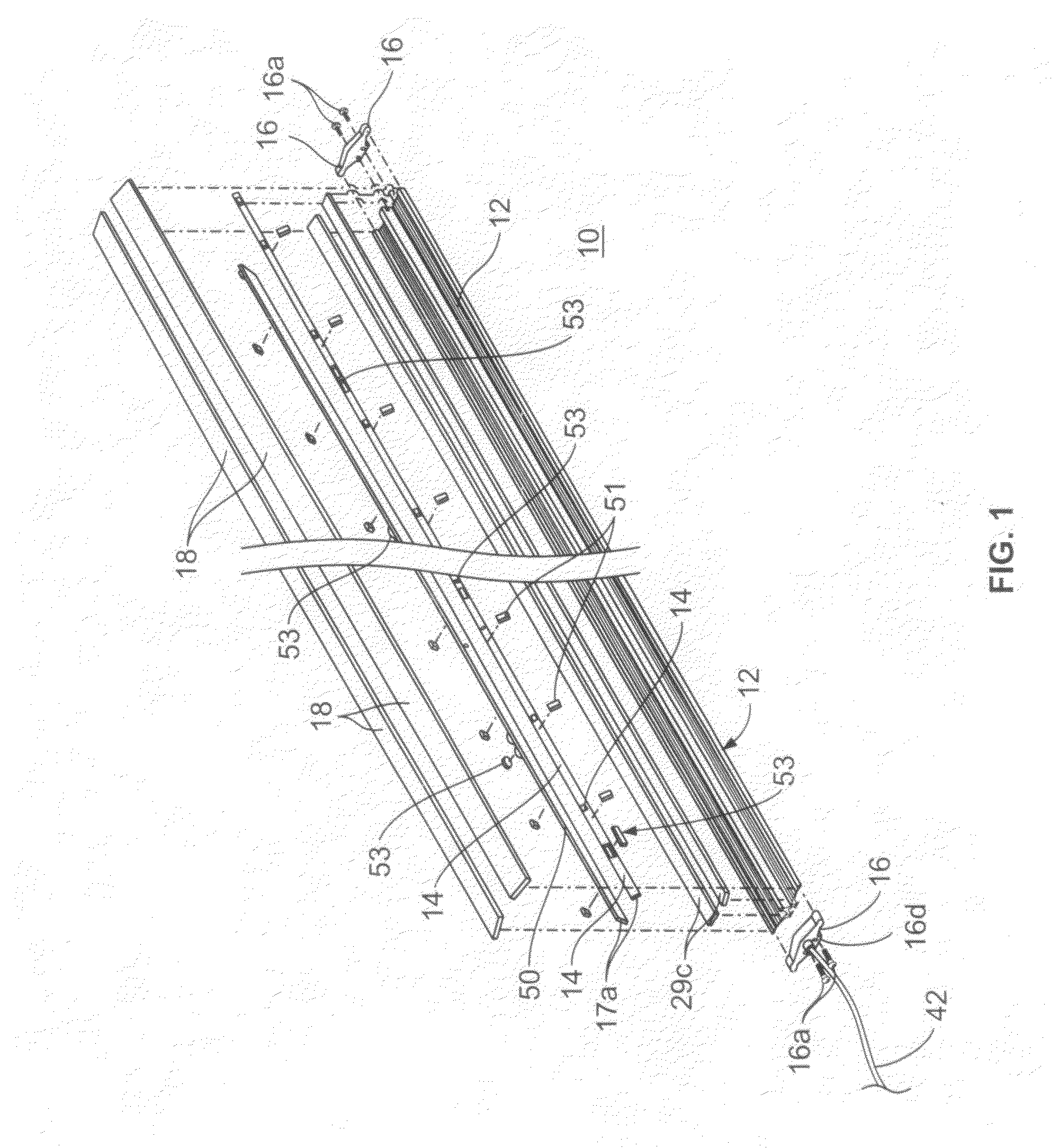
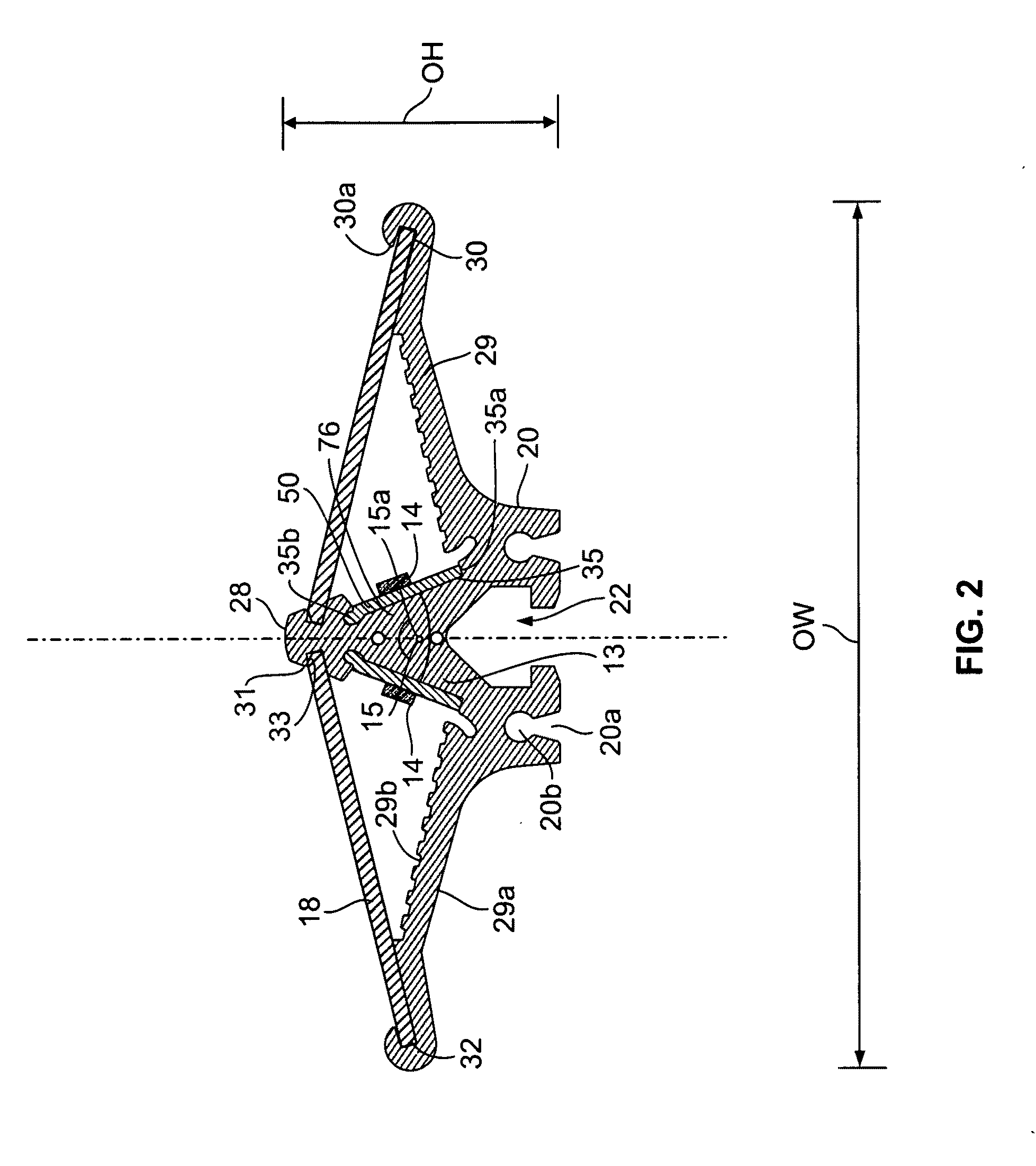
[0022]FIGS. 1-2 show an LED illuminated support fixture 10 of the present invention that is configured to be secured to an existing frame member or mullion within a display case or walk-in cooler, in a retrofit manner. Conventional refrigerated display cases are disclosed in U.S. Pat. Nos. 6,637,093 and 6,606,833. The fixture 10 comprises an elongated housing or frame 12, at least two light emitting diodes (LEDs) 14 electrically and mechanically connected to a printed circuit board (PCB) 50, angularly mounted within the frame 12, opposed end caps 16, and generally transparent ...


PUM


Abstract

The invention provides an elongated lighting fixture with multiple light emitting diodes (LEDs) arrayed in two groups that are angled to each other. The fixture provides an extremely broad light emitting angle and includes an elongated housing having a pair of side walls. Each side wall has a support member extending upward at angle from the side wall, wherein the side walls terminate at a central wall. A generally transparent cover is connected to the housing and extends between opposed ends of the housing. A first group of LEDs and a second group of LEDs are mounted to the first support member and the second support member, respectively. PCB boards assemblies are affixed to respective support members beneath the group of LEDs by tension clips. When the PCBs are energized by a power source, current travels from the PCBs to each LED for illumination.

Description

CROSS-REFERENCE TO RELATED APPLICATIONS[0001]This Application claims the benefit of U.S. Provisional Application No. 61 / 195,399, filed Oct. 7, 2008, and is a continuation-in-part of prior U.S. patent application Ser. No. 11 / 821,793, filed on Jun. 25, 2007, which claims the benefit of U.S. Provisional Application No. 60 / 187,913, filed Jun. 30, 2006.FEDERALLY SPONSORED RESEARCH OR DEVELOPMENT[0002]Not applicable.TECHNICAL FIELD[0003]The invention relates to an elongated lighting fixture with multiple light emitting diodes (LEDs) arrayed in two distinct angular positions. The fixture includes an elongated housing with two angled support members to which an array of LED modules are mounted, a circuit board affixed to a surface of each support member, a cover, and a power supply. The fixture may also include remote operations capability.BACKGROUND OF THE INVENTION[0004]There currently exists a number of lighting fixtures utilizing LEDs as the light source. While such fixtures provide som...

Claims


Application Information

Patent Timeline
Patent Type & Authority Applications(United States)
IPC IPC(8): F21V1/00
CPCF21S4/008F21V15/013F21V15/015F25D27/00F21W2131/405F21Y2101/02F21Y2103/003F21W2131/305F21S4/28F21Y2103/10F21Y2115/10
Inventor THOMAS, JAMESVOLOCHINE, VLADIMIR
Owner ELECTRALED
Why Eureka
Try Eureka