Broaching tool, in particular keyway broaching tool

a keyway broaching and tool technology, applied in the field of keyway broaching tools, can solve the problems of slim design of the shank, affecting the structural strength, and unable to meet both of these requirements, and achieve the effect of strengthening the structure of the shank

Active Publication Date: 2010-04-29
HARTMETALL WERKZEUGFAB PAUL HORN
View PDF10 Cites 9 Cited by
  • Summary
  • Abstract
  • Description
  • Claims
  • Application Information

AI Technical Summary

Benefits of technology

[0014]In advantageous exemplary embodiments, the cutting body has a parent member in the form of a plate which is to be accommodated in the passage of the shank and whose wide sides opposite one another form bearing surfaces for the guide surfaces of the passage. Due to such bearing against the inside of the passage over a large area, the parent member of the cutting body especially helps to reinforce the structure of the shank.
[0015]In such exemplary embodiments, the clamping device can advantageously have a clamping screw which passes through a hole in the parent member of the cutting body, said hole running perpendicularly to the wide sides, defining parallel planes, of said parent member, wherein, for the clamping screw, a tapped hole is provided on the shank in one of the guide surfaces of the passage. This configuration opens up the advantageous possibility of realizing on the cutting body, in a simple manner in terms of design, the desired force component for bearing against the end-position limit by the relative positional arrangements of the hole in the parent member of the cutting body, of the tapped hole in the passage of the shank and of the end-position limit for the cutting body being selected in such a way that the tightening of the clamping screw produces both a clamping force and the force component which acts in the insertion direction and presses the projecting surface part of the cutting body against the counter-stop of the passage in the desired manner or presses the slope of the cutting body against the sloping surface of the passage of the shank.

Problems solved by technology

Both of these requirements cannot be easily met, in particular if the broaching tool, in particular during use as a keyway broaching tool, is intended for internal machining in a bore of a workpiece or in a hollow body.
If the machining is to be carried out in bores having a relatively small diameter, this inevitably results in a slim, elongated design for the shank, a factor which is detrimental to the structural strength.
In addition to this problem there is also the fact that the design of the seat for the cutting body results in a local reduction in the load-bearing material cross section of the shank, a factor which likewise impairs the structural strength.

Method used


Image

  • Broaching tool, in particular keyway broaching tool
  • Broaching tool, in particular keyway broaching tool
  • Broaching tool, in particular keyway broaching tool

Examples


Embodiment Construction

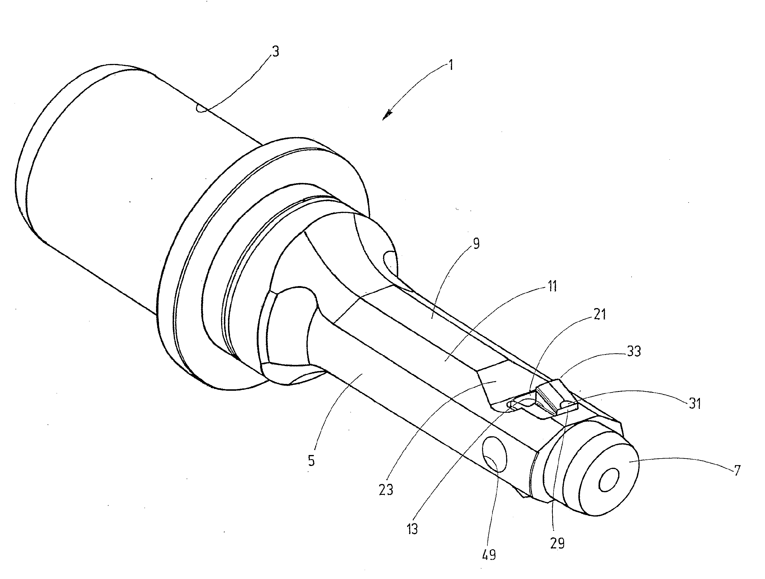
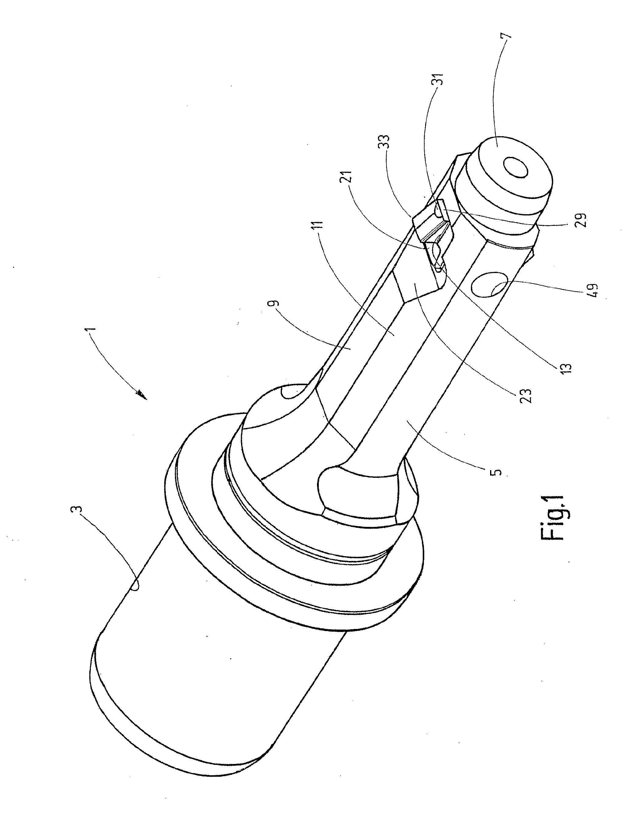
[0032]The holder 1, designated by 1 overall in FIGS. 1 and 3, has a rear clamping part 3 with which the broaching tool can be clamped in place in a machine tool (not shown), by means of which the tool can be moved in the direction of the tool longitudinal axis 4 (FIGS. 3 and 6) for a reciprocating broaching operation in the forward direction and rearward direction. Adjoining the clamping part 3 is a shank 5, which is narrowed relative to the clamping part 3 and the front shank end of which is designated by 7. Whereas the clamping part 3 is by and large of circular-cylindrical shape, the outer surface of the shank 5 has contouring with flat surface regions 9 and 11, see in particular FIG. 1. At a small distance from the front end 7, the shank 5 has a passage 13, the inside of which forms guide surfaces for a cutting body which can be inserted in an insertion direction and is depicted overall by 15 in the figures. Further details of the cutting body 15 are illustrated in particular in...


PUM

PropertyMeasurementUnit
distanceaaaaaaaaaa
forceaaaaaaaaaa
surface qualityaaaaaaaaaa

Abstract

The invention relates to a broaching tool, in particular a keyway broaching tool, comprising a holder which defines a longitudinal axis and has a shank, extending in the longitudinal direction, as support for a cutting body which can be fixed in a seat of the shank by means of a clamping device. The seat has a passage which is at a distance from the free end of the shank and extends transversely to the longitudinal axis and the inside of which forms guide surfaces for bearing surfaces of the cutting body, which can be inserted into the passage in an insertion direction. An end-position limit for the inserted cutting body is formed on guide surfaces and on associated bearing surfaces. The clamping device produces a force component on the cutting body which presses the latter against the end-position limit.

Description

CROSS-REFERENCE TO RELATED APPLICATIONS[0001]This is a Continuation application of International patent application PCT / IB 2008 / 001076, filed Feb. 13, 2008, which claims the priority of German patent application DE 10 2007 008 081 filed Feb. 17, 2007.BACKGROUND OF THE INVENTION[0002]1. Brief Summary of the Invention[0003]The invention relates to a broaching tool, in particular a keyway broaching tool, comprising a holder which defines a longitudinal axis and has a shank, extending in the longitudinal direction, as support for a cutting body which can be fixed in a seat of the shank by means of a clamping device.[0004]2. Related Prior Art[0005]If such broaching tools are used for machining operations in which the highest accuracy and high surface quality are required, two main requirements have to be met. Firstly, it must be ensured through high strength of the shank that forces and moments, in particular bending moments, which are introduced into the seat via the cutting body are ab...

Claims


Application Information

Patent Timeline
Patent Type & Authority Applications(United States)
IPC IPC(8): B23D37/00
CPCB23D7/06B23D13/005Y10T409/4077Y10T407/1628Y10T407/16
Inventor SCHAEFER, HANS
Owner HARTMETALL WERKZEUGFAB PAUL HORN
Why Eureka
Try Eureka