Composite PTFE Materials and Applications Thereof

Inactive Publication Date: 2010-04-29
POREX CORP
View PDF46 Cites 35 Cited by
  • Summary
  • Abstract
  • Description
  • Claims
  • Application Information

AI Technical Summary

Benefits of technology

[0005]In view of the foregoing disadvantages, the present invention provides composite PTFE materials that demonstrate superior homogeneity and resistance to dissociation into composite components. In some embodiments, the composite PTFE materials of the present invention are

Problems solved by technology

However, properties such as high melt viscosity and high crystallinity preclude PTFE from being processed by traditional techniques for plastics.
Compounding PTFE with various materials, for example, can be difficult often resulting in substantial inhomogeneity in the final product.
Moreover, the resistance of PTFE to adhere to other materials presents significant challenges in producing composite PTFE materials that do not dissociate when subjected to various environmental stresses.
Furthermore, the non-porous nature of PTFE produced by established methods presents additional difficulties in using this material in applications wherein porous materials are required, in

Method used


Image

  • Composite PTFE Materials and Applications Thereof
  • Composite PTFE Materials and Applications Thereof
  • Composite PTFE Materials and Applications Thereof

Examples


example 1

Composite Particles Comprising a PTFE Component and a Carbonaceous Component

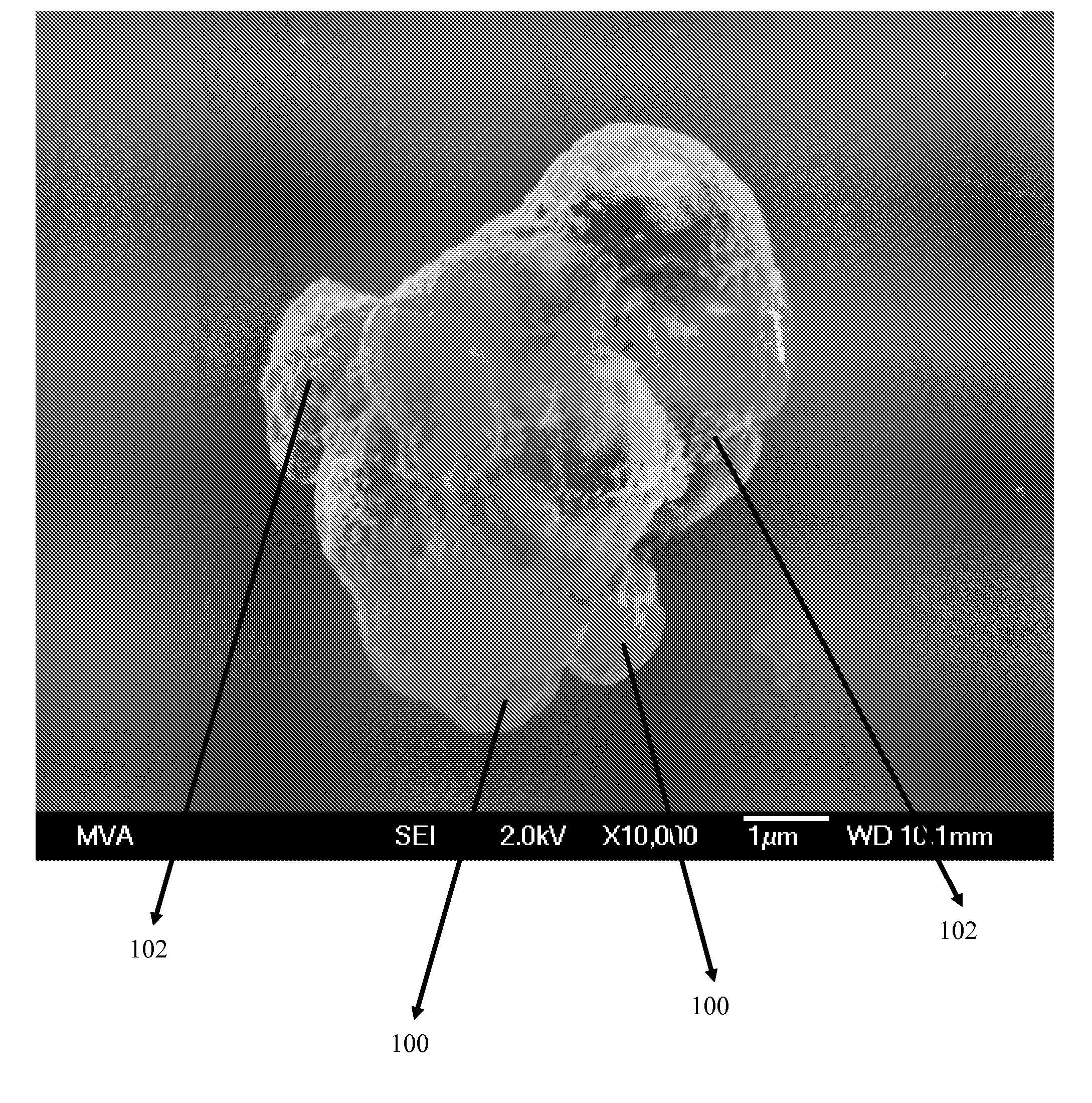
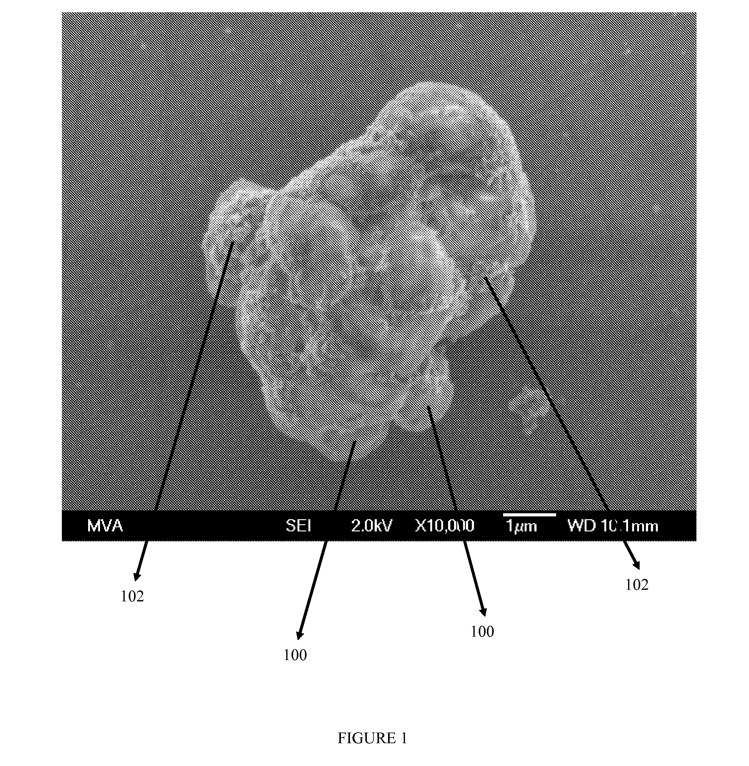
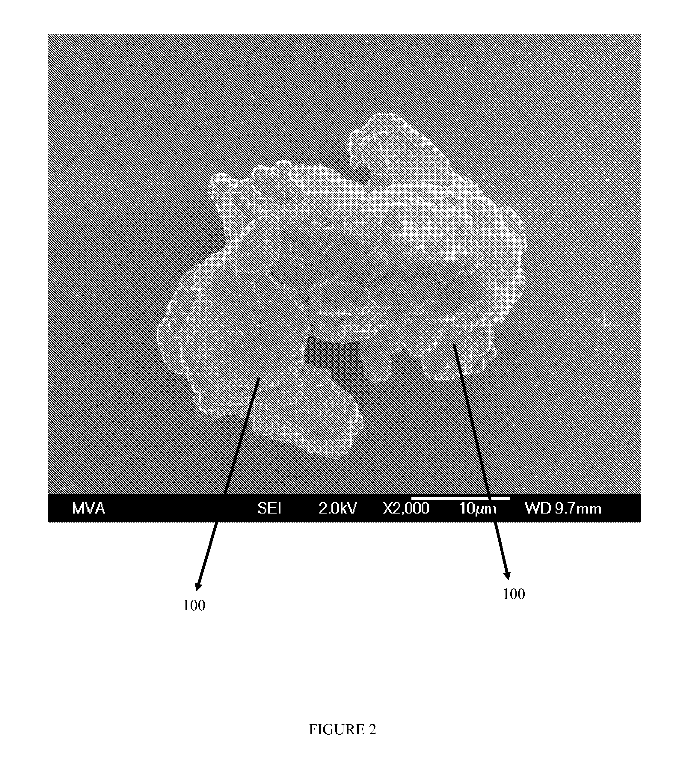
[0066]A mixture of PTFE particles (PTFE component) and carbon black (carbonaceous component) was obtained from 3M (St. Paul, Minn.) under the trade designation Dyneon. The PTFE-carbon black mixture comprised 1.2 weight percent carbon black particles. Consistent with FIG. 1, the carbon black resided on the exterior surfaces of the PTFE particles. The PTFE-carbon black mixture was placed into a flat mold having an area of 600 mm×700 mm and heated to a temperature of 340° C. for about two hours under ambient pressure. The mold was subsequently cooled to room temperature and the black PTFE slab was removed from the mold. The black PTFE slab was ground to form composite particles having an average size of about 60 μm. Consistent with the composite particles shown in FIG. 2, the carbon black was fused into and dispersed throughout the PTFE particles as described herein.

example 2

Membrane Comprising a Plurality of Sintered Composite Particles

[0067]The composite particles of Example 1 were placed into a pressure mold as described in U.S. Pat. No. 5,514,231 at a pressure of about 60 bar. The mold was heated to 360° C. for about 8 hours. The mold was subsequently cooled to room temperature and a sintered porous composite black PTFE cylinder was removed from the mold. A composite membrane was prepared by skiving the cylinder. The sintered composite black PTFE membrane had an average pore size of 5 μm. The average pore volume of the membrane was about 40%. The membrane had a spectral reflectance of less than 20%.

example 3

Membrane Comprising a First Surface and a Second Surface

[0068]A PTFE membrane comprising a white surface and a black surface was constructed according to the following procedure. A white PTFE membrane was made in a similar manner to the black PTFE membrane by using the pure PTFE particles. The white PTFE membrane was laminated to the sintered black composite PTFE membrane of Example 2 by providing a polyamide based adhesive fabric between the white and black PTFE membranes. The resulting structure was subsequently heated to a temperature of 130° C. under pressure to produce a unitary membrane comprising a white side having a spectral reflectance greater than 90% and a black side having a spectral reflectance of less than 20%. The membrane had an average pore size of 5 μm. The average pore volume of the membrane was about 40%.


PUM

PropertyMeasurementUnit
Temperatureaaaaaaaaaa
Pore sizeaaaaaaaaaa

Abstract

The present invention provides sintered composite polymeric materials and methods of making and using the same. The sintered composite polymeric materials are made by sintering composite particles comprising a polytetrafluoroethylene component and a carbonaceous component, wherein the carbonaceous component is dispersed throughout the polytetrafluoroethylene component.

Description

PRIOR RELATED APPLICATIONS[0001]The present application claims the benefit of priority to U.S. Provisional Application No. 61 / 108,372 filed Oct. 24, 2008 which is hereby incorporated by reference in its entirety.FIELD OF THE INVENTION[0002]The present invention relates to composite porous polymeric materials comprising sintered composite particles comprising a polytetrafluoroethylene (PTFE) component and a carbonaceous component dispersed in the PTFE component.BACKGROUND OF THE INVENTION[0003]The unique properties of PTFE, such as its outstanding electrical resistance, low coefficient of friction, chemical inertness, and non-support of combustion, have resulted in the use of PTFE in a wide range of applications. However, properties such as high melt viscosity and high crystallinity preclude PTFE from being processed by traditional techniques for plastics. Compounding PTFE with various materials, for example, can be difficult often resulting in substantial inhomogeneity in the final ...

Claims


Application Information

Patent Timeline
IPC IPC(8): B32B3/26B29B9/12B29C70/00C08L27/12C08L75/00C08K3/04
CPCY10T428/2982C08J9/0066B01D2323/08B01D67/0041B29C67/205B01D67/0079B01D71/36B01D71/26B01D67/0004B65D2585/86B01D71/021B01D69/12B29K2995/0065C08J9/24B01D69/148B29K2027/18B29K2995/0068B29L2031/755C08J2327/18B29L2031/14B01D2323/10Y10T428/249921Y10T428/249953Y10T428/249986Y10T428/249987Y10T428/249991Y10T428/3154Y10T428/31544
Inventor MACLENNAN, ANDREW JAMESAVETT, TRIPP AUGUSTUSLI, XINGGUOMAO, GUOQIANG
Owner POREX CORP
Why Eureka
Try Eureka