Motor and endoscope probe equipped with motor

a technology of endoscope probe and motor, which is applied in the direction of instruments, catheters, gearing, etc., can solve the problems of difficult to achieve biometric function imaging, low spatial resolution, radiation exposure, etc., to suppress the increase in diameter of endoscope probe, shorten the inflexible portion of the front end of the endoscope probe, and prevent the disconnection of the electric power supply wire

Inactive Publication Date: 2010-04-29
NAMIKI PRECISION JEWEL CO LTD
View PDF8 Cites 27 Cited by
  • Summary
  • Abstract
  • Description
  • Claims
  • Application Information

AI Technical Summary

Benefits of technology

[0046]According to claims 1, 2, 18, 19 and 34 of the present invention, since the electric power supply wire is led out in the direction in which the shaft of the motor projects or the direction in which the output shaft of the gear head projects, when the motor is mounted in the endoscope probe and the electric power supply wire is routed in the endoscope probe body, the electric power supply wire may not be bent. Accordingly, it is possible to prevent disconnection of the electric power supply wire and solve generation of R (corner R) of a bent portion generated due to bending. Therefore, it is possible to suppress the increase in diameter of the endoscope probe and to shorten an inflexible portion of the front end of the endoscope probe.
[0047]According to the motor described in claim 1, since the electric power supply wire is received in the cutout and led out to the outside of the motor, it is possible to prevent protrusion of the electric power supply wires in the diameter direction of the motor. Even in this case, it is possible to suppress the increase in diameter of the endoscope probe.
[0048]According to the motor described in claim 2, since the flat portion is formed on the outer circumferential surface of the flange and the electric power supply wire is placed on the flat portion, it is possible to prevent protrusion of the electric power supply wires in the diameter direction of the motor. Therefore, it is possible to suppress the increase in diameter of the probe.
[0049]According to the motor described in claim 3 or 4, since the flange functions as the shaft bearing, the number of parts included in the diameter direction of the motor can be reduced and thus the motor and the endoscope probe can be further downsized.
[0050]According to the motor described in claim 5, since the electric power supply wire is led out from only the circumference of one side of the motor to the outside of the motor, the number of electric power supply wires which become an obstacle at the time of scanning of the probe can be reduced and thus the rotation angle of the scanning shaft or output shaft is enlarged.
[0051]According to the motor described in claim 6 or 7, when the endoscope probe is scanned at a rotation angle of 360 degrees, it is possible to prevent the electric power supply wire of the motor from becoming an obstacle to scanning.

Problems solved by technology

However, if the X-rays are used, a problem such as exposure to radiation occurs or imaging of a biometric function is hard to be achieved.
However, since the ultrasonic endoscope probe has low spatial resolution, information such as physiologic compositions other than a shape cannot be obtained.
In addition, when the ultrasonic endoscope probe is used, since a medium such as water is required, a process of observing the subject is troublesome.

Method used


Image

  • Motor and endoscope probe equipped with motor
  • Motor and endoscope probe equipped with motor
  • Motor and endoscope probe equipped with motor

Examples


first embodiment

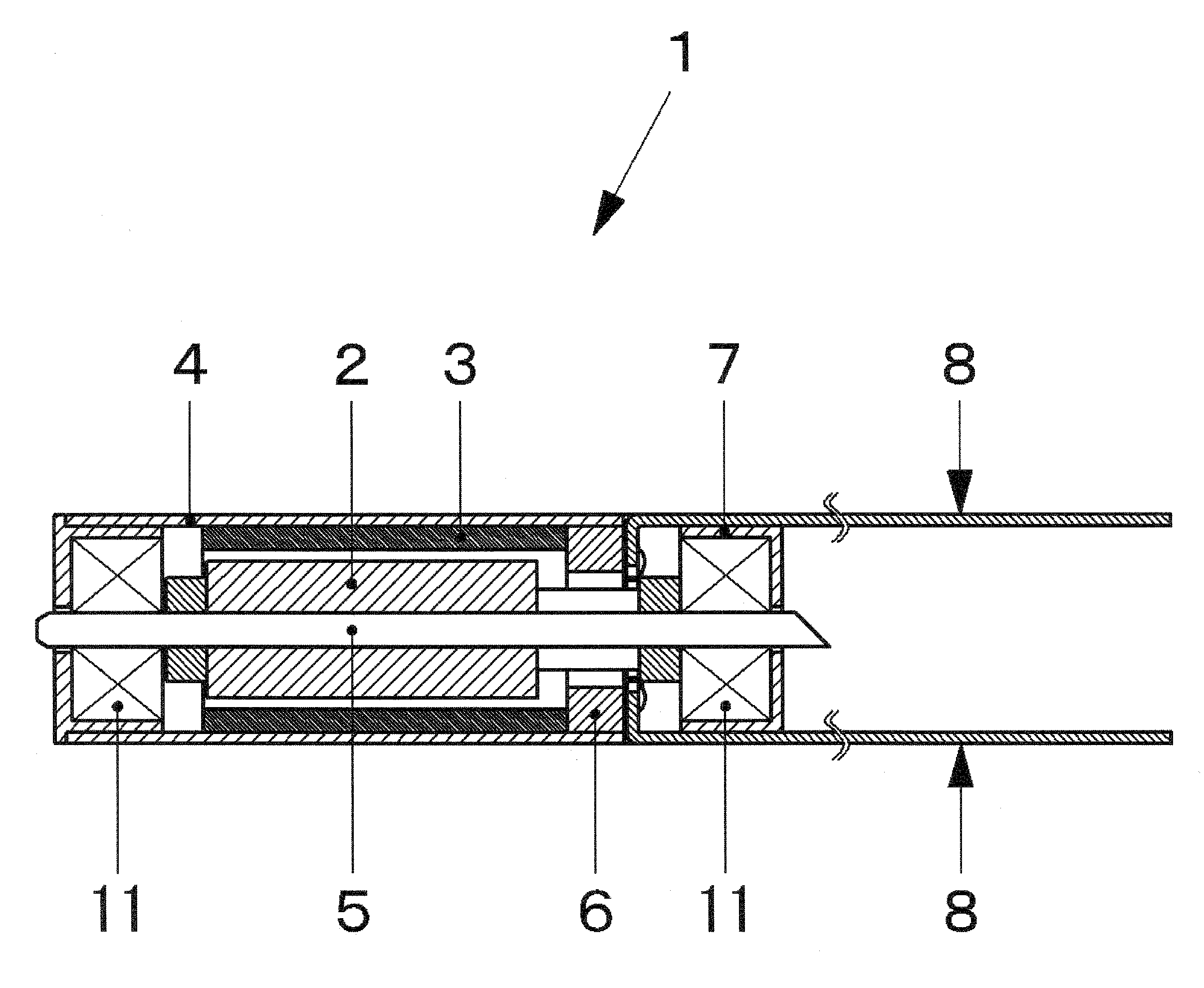
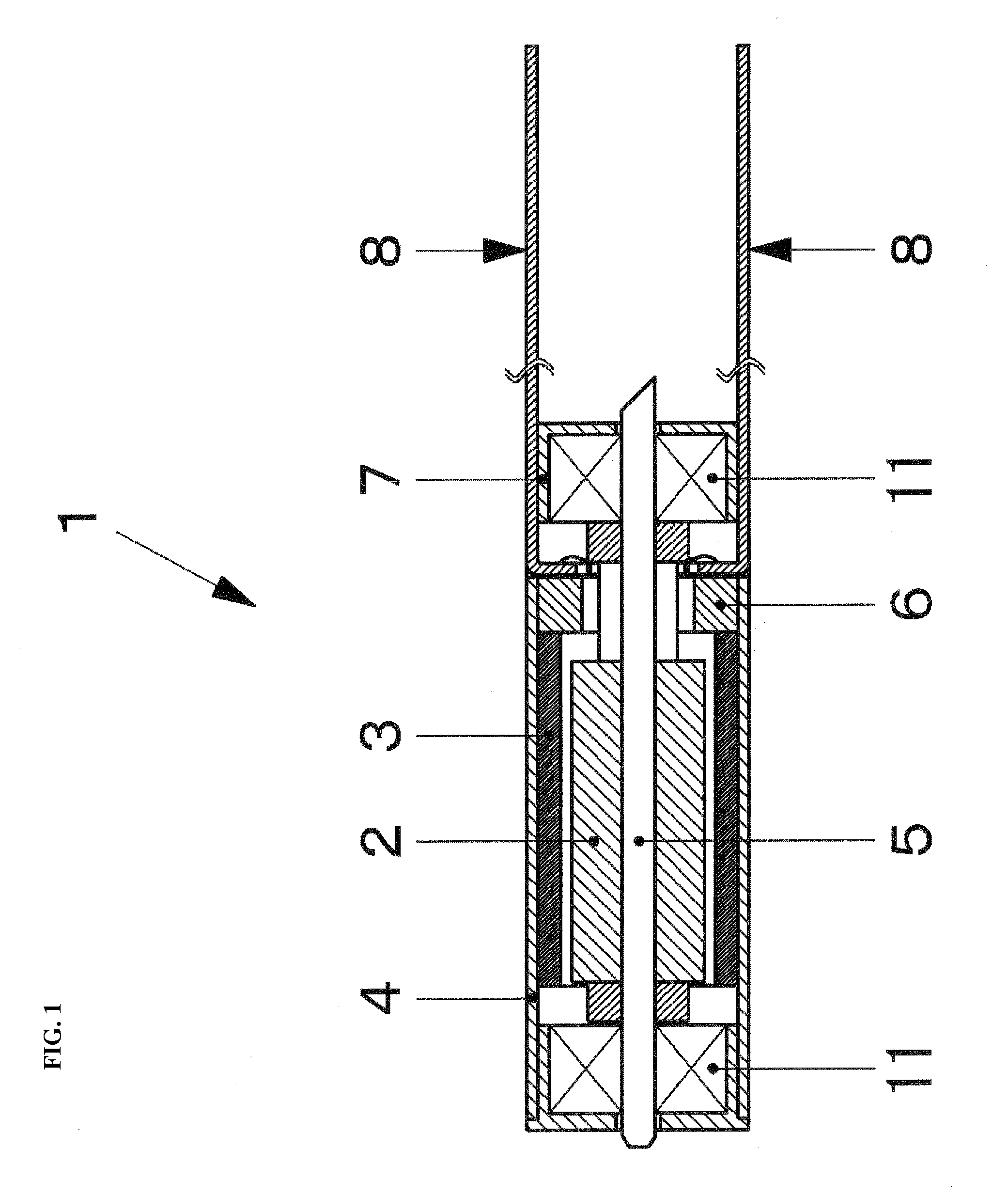
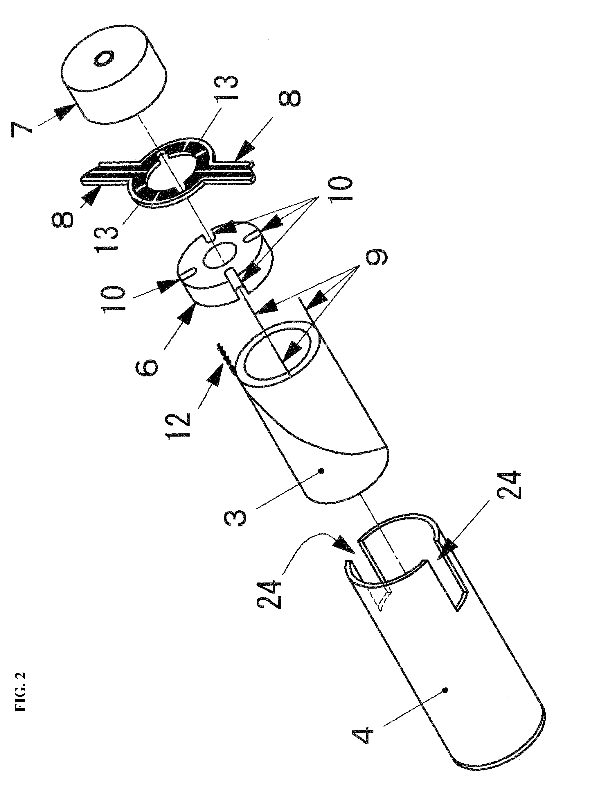
[0136]Hereinafter, a first embodiment of a motor and an endoscope probe according to the present invention will be described in detail with reference to FIGS. 1 to 5. FIG. 1 is a cross-sectional view of the motor according to the first embodiment. FIG. 2 is an exploded perspective view showing the structure of a stator of the motor of FIG. 1. FIG. 3 is a side view of the motor of FIG. 1. FIG. 4 is a schematic view of the internal structure of the endoscope in which the motor of FIG. 1 is mounted and, more particularly, an OCT endoscope probe. FIGS. 5A and 5B are partial enlarged views of an end of a shaft of the motor of FIG. 1.

[0137]In FIG. 1, the motor 1 includes a magnet 2, a field coil 3, a housing 4, flexible substrates 8 functioning as electric power supply wires, a shaft 5. In FIG. 2, the stator of the motor 1 includes the housing 4, the field coil 3, a lead wire guide 6, a flange 7 and the flexible substrates 8.

[0138]The appearance of the housing 4 has a substantially cylind...

second embodiment

[0169]Hereinafter, a second embodiment of a motor and an OCT endoscope probe according to the present invention will be described in detail with reference to FIGS. 6 to 8. FIG. 6 is a cross-sectional view of the motor according to the second embodiment. FIG. 7 is an exploded perspective view showing the structure of a stator of the motor of FIG. 6. FIG. 8 is a schematic view of the internal structure of the endoscope probe in which the motor of FIG. 6 is mounted and, more particularly, the OCT endoscope probe. In the description of the motor 18 according to the second embodiment, the portions overlapping with those of the motor 1 are denoted by the same reference numerals and the description thereof will be omitted or simplified. The stator of the motor 18 includes a housing 19, a field coil 3, a lead wire guide 20, a flange 21 and flexible substrates 22 and 23.

[0170]The appearance of the housing 19 has a substantially cylindrical shape and cutouts 24 and 24 are formed in an end the...

third embodiment

[0186]Hereinafter, a third embodiment of a motor and an OCT endoscope probe according to the present invention will be described in detail with reference to FIGS. 9 to 11. FIG. 9 is a cross-sectional view of the motor according to the third embodiment. FIG. 10 is an exploded perspective view showing the stator structure of the motor in FIG. 9. FIG. 11 is a schematic view of the internal structure of an endoscope probe in which the motor of FIG. 9 is mounted and, more particularly, the OCT endoscope probe. In the description of the motor 44 according to the third embodiment, the portions overlapping with those of the motor 18 of the second embodiment are denoted by the same reference numerals and the description thereof will be omitted or simplified.

[0187]The motor 44 of the present embodiment is different from the motor 18 of the second embodiment in that the cutouts 24 and 24 are not formed and thus the appearance of a housing 45 has a substantially cylindrical shape. When the flex...


PUM


Abstract

A motor which can be mounted in an endoscope probe without bending an electric power supply wire in an endoscope probe body, and an endoscope probe using the motor are provided. The motor includes a magnet, a field coil, a housing, an electric power supply wire, and a shaft. A lead wire from the field coil is connected to the electric power supply wire. A cutout is provided in a housing end, and the electric power supply wire is received along the cutout and led out to the outside of the motor in the direction in which a shaft projects. When the motor is mounted in the endoscope probe, the motor is placed in the endoscope probe body so that the shaft projects in the direction opposite to the direction of the front end of the endoscope probe, and the electric power supply wire, which is led out to the outside of the motor, is routed along the longitudinal direction of the endoscope probe.

Description

TECHNICAL FIELD[0001]The present invention relates to a motor used in an endoscope probe and an endoscope probe equipped with the motor.RELATED ART[0002]Recently, as the use of an image in diagnosis has spread, importance of a technique for measuring internal information of a subject in a non-invasive or non-contact manner has been gradually increased.[0003]Conventionally, the non-invasive or non-contact measurement of the internal information of the subject such as an organism was mainly performed by X-rays. However, if the X-rays are used, a problem such as exposure to radiation occurs or imaging of a biometric function is hard to be achieved. Accordingly, observation of a tissue inside a body cavity by an ultrasonic endoscope probe has been performed.[0004]However, since the ultrasonic endoscope probe has low spatial resolution, information such as physiologic compositions other than a shape cannot be obtained. In addition, when the ultrasonic endoscope probe is used, since a med...

Claims


Application Information

Patent Timeline
Patent Type & Authority Applications(United States)
IPC IPC(8): A61B1/00H02K11/00G02B26/10H02K7/116
CPCA61B1/00096A61B1/00133A61B1/00172A61B5/0066A61B5/0084A61B5/6852H02K2211/03A61B2019/5278F16H1/46G02B23/2476H02K5/225H02K7/116H02K7/14A61B2019/5234A61B2090/3735A61B2090/3782
Inventor SHIMIZU, YUKIHARUNAKAMURA, KAZUYATAKANO, TSUYOSHI
Owner NAMIKI PRECISION JEWEL CO LTD
Why Eureka
Try Eureka