Systems and Methods for Disconnecting Electrodes of Leads of Implantable Medical Devices During an MRI to Reduce Lead Heating

a technology of medical devices and electrodes, applied in the field of lead electrode disconnection systems and methods, can solve the problems of affecting the safety of patients with implantable medical devices such as pacemakers, affecting the safety of patients, and damaging adjacent tissues or the lead itsel

Inactive Publication Date: 2010-04-29
PACESETTER INC
View PDF34 Cites 25 Cited by
  • Summary
  • Abstract
  • Description
  • Claims
  • Application Information

AI Technical Summary

Benefits of technology

[0009]In accordance with various embodiments of the invention, a lead is provided for use with an implantable medical device for generating stimulation pulses for delivery to tissues of a patient. A switch is provided within the lead for disconnecting a first electrode of the lead (e.g. a tip electrode) from its conductor in the presence of particular electromagnetic fields, such as the fields of an MRI, but not during delivery of actual stimulation pulses. For example, a tip switch is opened upon detection of an MRI and kept open during the MRI—except duri...

Problems solved by technology

However, MRI procedures are problematic for patients with implantable medical devices such as pacemakers and ICDs.
A significant problem is that the strong fields of the MRI can induce currents within the lead system that cause the electrodes of leads of the implantable device to become significantly heated, potentially damaging adjacent tissues or the lead itself.
Although such a dramatic increase is probably unlikely within a system, wherein leads are properly implanted, even a temperature increase of only about 8°-13° C. can cause myocardial tissue damage.
Furthermore, any significant heating of the electrodes of pacemaker and ICD leads, particular tip electrodes, can affect pacing and sensing parameters...

Method used


Image

  • Systems and Methods for Disconnecting Electrodes of Leads of Implantable Medical Devices During an MRI to Reduce Lead Heating
  • Systems and Methods for Disconnecting Electrodes of Leads of Implantable Medical Devices During an MRI to Reduce Lead Heating
  • Systems and Methods for Disconnecting Electrodes of Leads of Implantable Medical Devices During an MRI to Reduce Lead Heating

Examples


Embodiment Construction

[0033]The following description includes the best mode presently contemplated for practicing the invention. The description is not to be taken in a limiting sense but is made merely to describe general principles of the invention. The scope of the invention should be ascertained with reference to the issued claims. In the description of the invention that follows, like numerals or reference designators will be used to refer to like parts or elements throughout.

Overview of MRI System

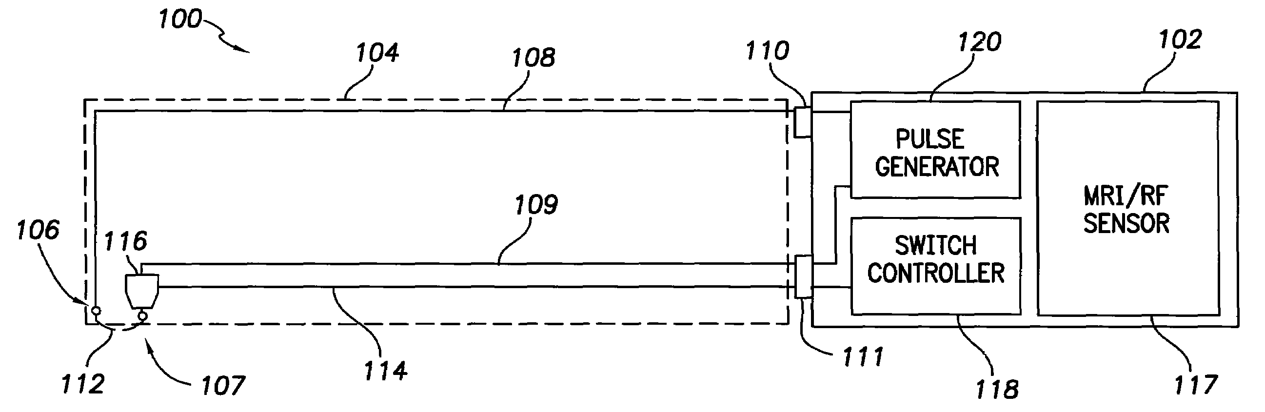
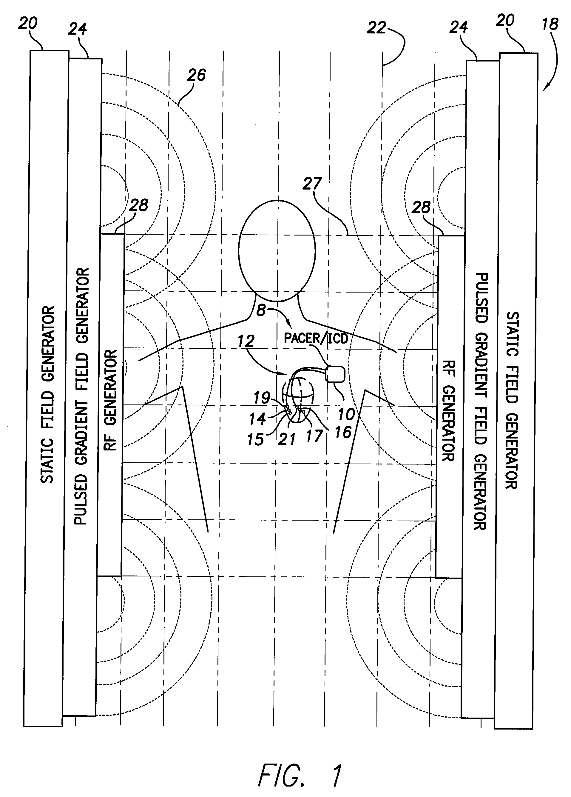
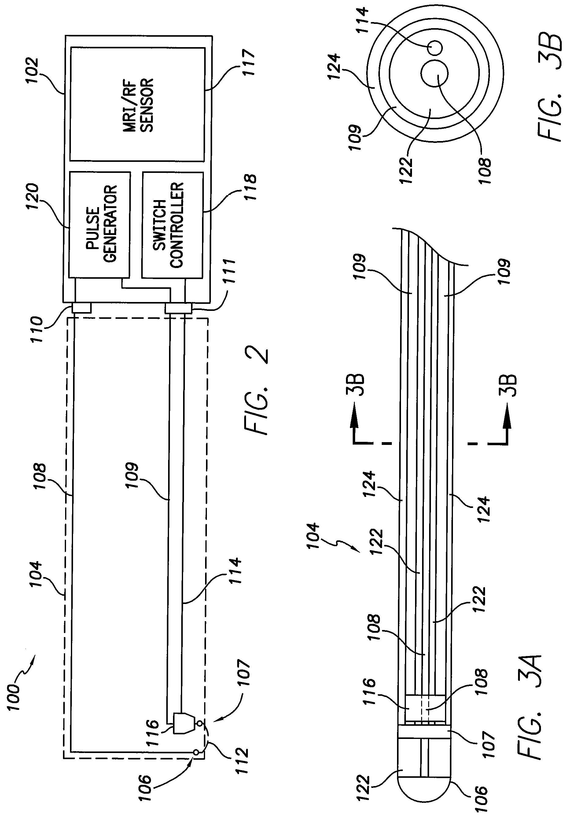
[0034]FIG. 1 illustrates an implantable medical system 8 having a pacer / ICD 10 for use with a set of coaxial bipolar pacing / sensing leads 12, which include tip and ring electrodes 14, 15, 16 and 17, as well as ring electrode switching elements 19 and 21. Switching circuitry within the pacer / ICD is operative to control the ring switches to electrically disconnect the ring electrodes from the pacing / ICD in the presence of MRI fields to reduce lead heating caused by magnetic fields generated by an MRI system...


PUM


Abstract

Systems and methods are provided for reducing heating within pacing/sensing leads of a pacemaker or implantable cardioverter-defibrillator that occurs due to induced loop currents during a magnetic resonance imaging (MRI) procedure, or in the presence of other sources of strong radio frequency (RF) fields. For example, bipolar coaxial leads are described herein wherein the ring conductor of the lead is disconnected from the ring electrode in response to detection of MRI fields so as to convert the ring conductor into an RF shield for shielding the inner tip conductor of the lead so as to reduce the strength of loop currents induced therein and hence reduce tip heating. Techniques are also described herein for selectively disconnecting the tip electrode of the lead during an MRI procedure, except during actual delivery of pacing pulses, so as to permit delivery of individual pacing pulses to pacemaker dependent patients during the MRI. Still other techniques describe the use of both RF shielding and tip switching.

Description

RELATED APPLICATIONS[0001]This application is related to copending U.S. patent application Ser. No. ______, filed concurrently herewith, entitled “Systems and Methods for Exploiting the Tip or Ring Conductor of an Implantable Medical Device Lead during an MRI to Reduce Lead Heating and the Risks of MRI-Induced Stimulation” (Attorney Docket No. A08P1048).FIELD OF THE INVENTION[0002]The invention generally relates to leads for use with implantable medical devices, such as pacemakers or implantable cardioverter-defibrillators (ICDs), and to techniques for reducing tip heating within such leads during a magnetic resonance imaging (MRI) procedure.BACKGROUND OF THE INVENTION[0003]MRI is an effective, non-invasive magnetic imaging technique for generating sharp images of the internal anatomy of the human body, which provides an efficient means for diagnosing disorders such as neurological and cardiac abnormalities and for spotting tumors and the like. Briefly, the patient is placed within ...

Claims


Application Information

Patent Timeline
IPC IPC(8): A61N1/05A61N1/372A61N1/36
CPCA61N2001/086A61N1/3718A61N1/086
Inventor MIN, XIAOYICHOLETTE, MARTINMOULDER, J. CHRISTOPHER
Owner PACESETTER INC
Why Eureka
Try Eureka