Workpiece detecting system, picking apparatus, picking method, and transport system
a technology of workpiece detection and transfer system, which is applied in the field of workpiece detection system, picking apparatus, picking method, and transfer system, can solve the problems of calculating the distance between feature points of workpieces using two images, and the method requires a lot of analysis time, so as to achieve the effect of detection in a short tim
- Summary
- Abstract
- Description
- Claims
- Application Information
AI Technical Summary
Benefits of technology
Problems solved by technology
Method used
Image

Examples
first embodiment
[0060]A picking apparatus including a workpiece detecting system and a picking method characteristic of a first embodiment of the invention will be explained in accordance with FIGS. 1 through 9. The picking method is a method for transferring a workpiece by grabbing, transferring, and releasing the workpiece. A picking apparatus is an apparatus for implementing the picking method.
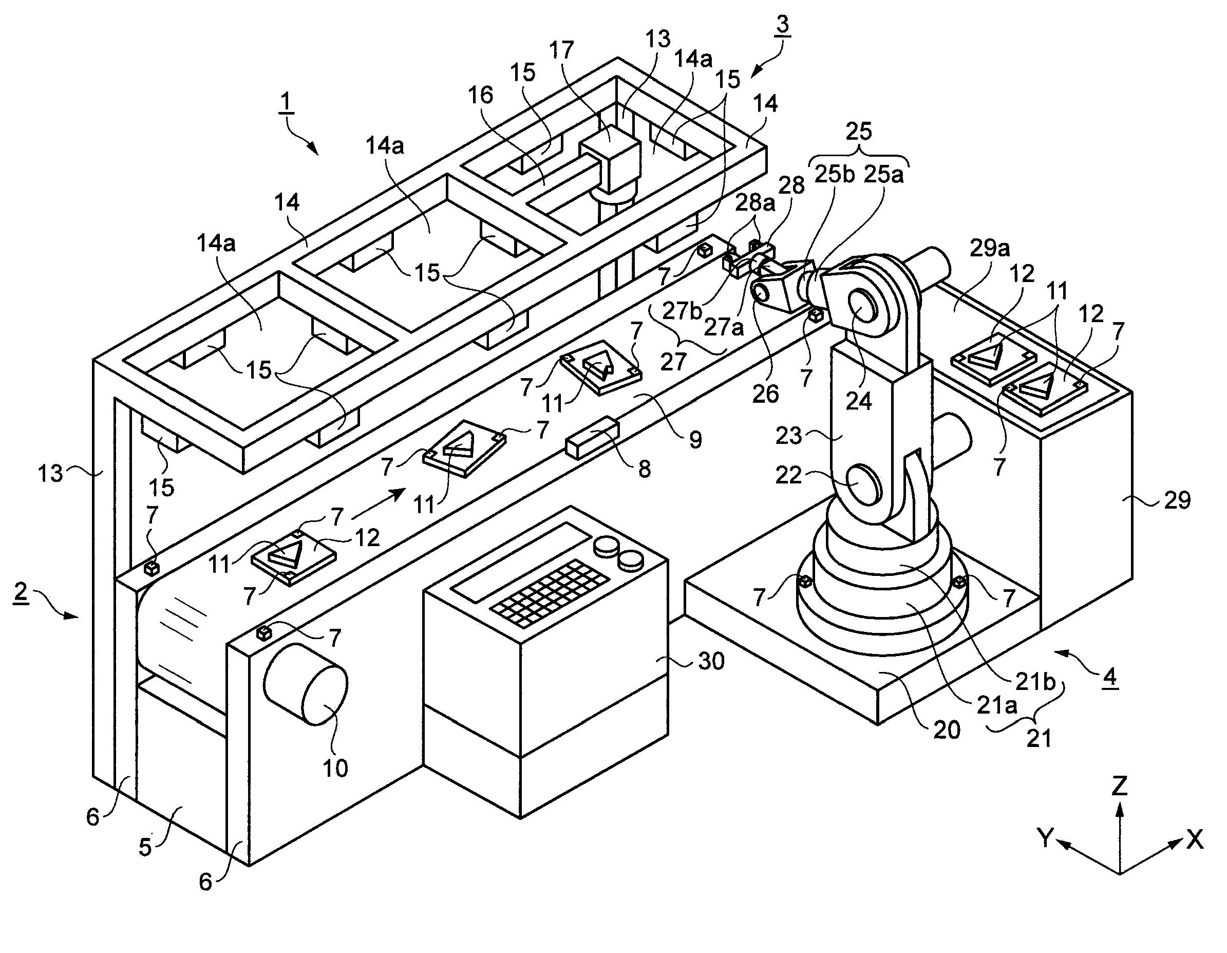
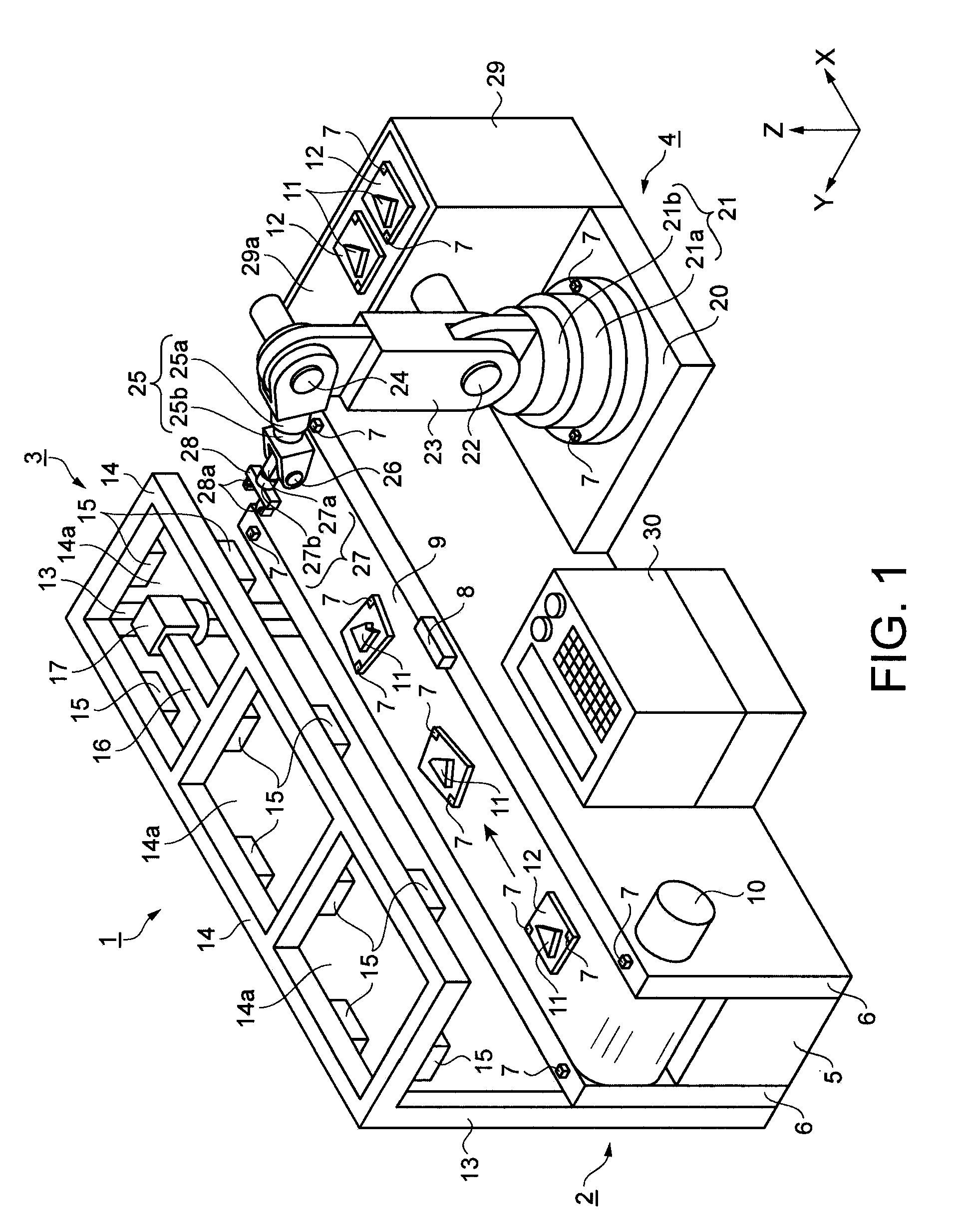
[0061]FIG. 1 is a perspective diagram schematically showing the structure of the picking apparatus. Referring to FIG. 1, a picking apparatus 1 mainly includes a conveyer 2, a position detecting unit 3, and a robot 4. The conveyer 2 has a base 5 which is formed long in one direction. A longitudinal direction of the base 5 is an X direction. A direction opposite from a gravitational direction is a Z direction, and a direction orthogonal to the X and Z directions is a Y direction.
[0062]A pair of sideboards 6 is disposed on both sides of the base 5 in the Y direction. Ultrasonic wave tags 7 are disposed on bot...
second embodiment
[0128]An embodiment of the picking method will now be described using FIGS. 10 through 11 as a second embodiment of the invention. This embodiment differs from the first embodiment in that the ultrasonic wave tags 7 are arranged in different patterns for every type of the workpiece 11. Description of similarities to the first embodiment will not be repeated.
[0129]FIGS. 10A through 10C are plan diagrams of the workpieces with the ultrasonic wave tags disposed thereon. In the present embodiment, with reference to FIGS. 10A through 10C, various types of workpieces 11 are used. The layout pattern of the tags 7 disposed on the workpiece supports 12 differs for each workpiece 11. A first workpiece 11a, a second workpiece 11b, and a third workpiece 11c are the workpieces 11 having different configurations. Each workpiece 11 is disposed on the workpiece support 12, and two tags 7 are disposed on front and rear surfaces of each workpiece support 12. A distance between the tags 7 on the front...
modified example 1
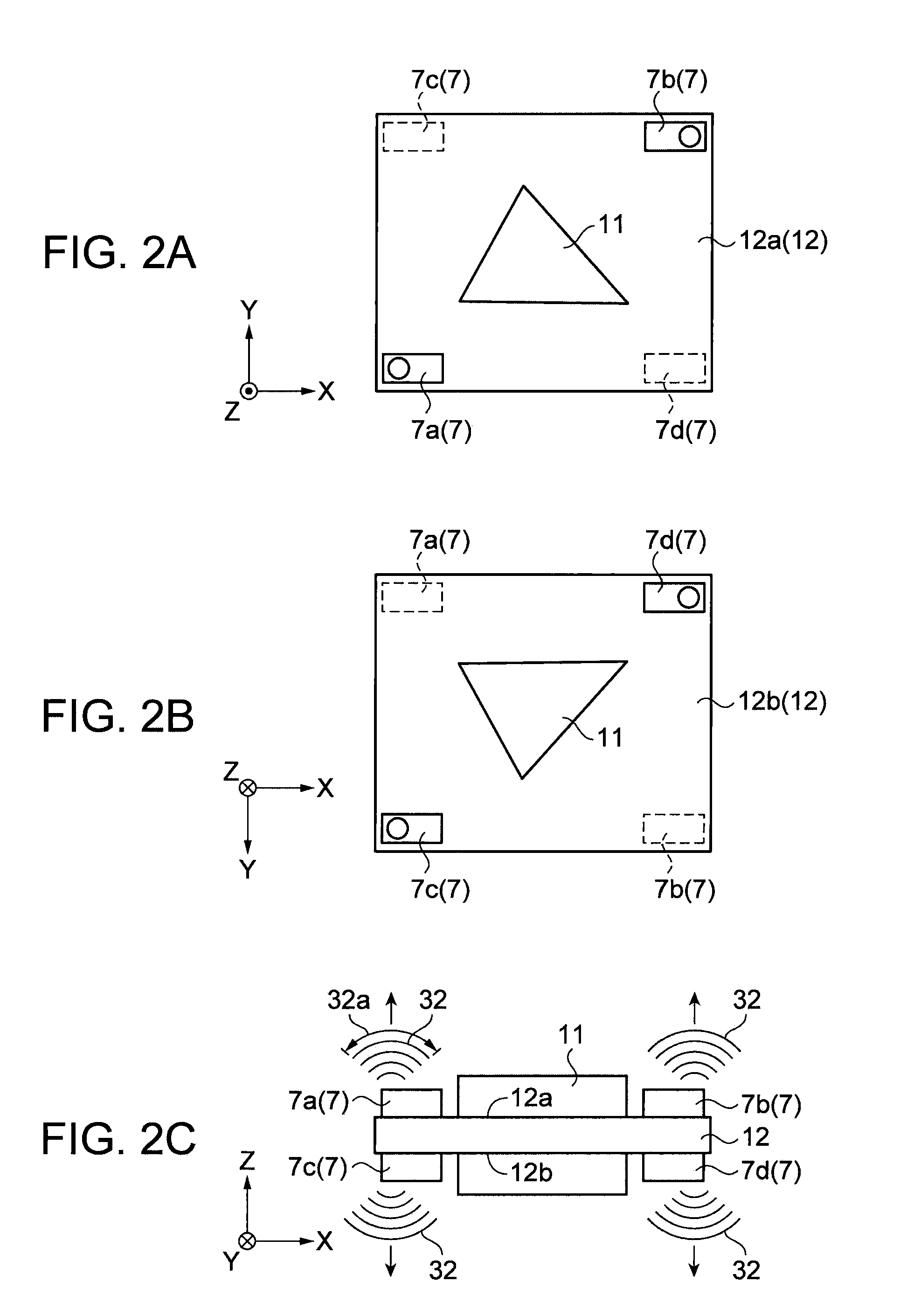
[0138]In the first embodiment, the ultrasonic wave tags 7 are disposed on the upper and lower surfaces 12a, 12b of the workpiece 11. The tags 7 may change the directions of sending the ultrasonic waves 32 in accordance with the configuration of the workpiece 11. FIGS. 12A and 12B are pattern diagrams of a workpiece 75. FIG. 12A is a plan pattern diagram showing the workpiece, and FIG. 12B is a side pattern view of the workpiece. Referring to FIGS. 12A and 12B, if the configuration of the workpiece 75 is a rectangular parallelpiped or the like that allows any of its surfaces to face upward, for example, it is possible to dispose the tags 7 in a direction corresponding to the direction of the surface of the workpiece 75 that may face upward. There are five pairs of tags 7 disposed on the upper surface 12a of the workpiece support 12. The waves 32 may be sent in directions of X, opposite from X, Y, opposite from Y, and Z. A pair of tags 7 is disposed on the lower surface 12b of the wor...
PUM
 Abstract
Description
Claims
Application Information
 - R&D
- Intellectual Property
- Life Sciences
- Materials
- Tech Scout
- Unparalleled Data Quality
- Higher Quality Content
- 60% Fewer Hallucinations
Browse by: Latest US Patents, China's latest patents, Technical Efficacy Thesaurus, Application Domain, Technology Topic, Popular Technical Reports.
© 2025 PatSnap. All rights reserved.Legal|Privacy policy|Modern Slavery Act Transparency Statement|Sitemap|About US| Contact US: help@patsnap.com