Control and systems for autonomously driven vehicles

a technology for autonomous driving and control systems, applied in the direction of distance measurement, instruments, and reradiation, etc., can solve the problems of driver's inability to perform all of these functions, driver's ability to become compromised, driver at risk,

Active Publication Date: 2010-04-29
SAMSUNG ELECTRONICS CO LTD
View PDF9 Cites 816 Cited by
  • Summary
  • Abstract
  • Description
  • Claims
  • Application Information

AI Technical Summary

Benefits of technology

[0022]In one embodiment of the invention, a navigation and control system includes one or more position sensors configured to generate position signals indicative of the location and heading of a vehicle. The system includes one or more operation control mechanisms having inputs and producing outputs which control an operation of the vehicle and includes a self-contained autonomous controller disposed remote from the operation control mechanisms. The autonomous controller includes a processor configured to receive the position signals from the position sensors and to generate operation control signals defining an updated travel path for the vehicle, and a programmable interface providing communication among the position sensors, the operation control mechanisms, and the processor. The programmable interface is configured to normalize inputs to the processor from the position sensors and to generate compatible operation control signals applied as the inputs to the operation control mechanisms, whereby the self-contained autonomous controller is configurable for operation with a variety of different sensors and different operation control mechanisms.

Problems solved by technology

Yet, the driver's ability to perform all of these functions can become compromised due to physical factors such as driver fatigue, driver impairment, driver inattention, or other factors such as visibility that reduce the reaction time needed by the driver to successfully avoid hazards.
Furthermore, in environmentally dangerous surroundings such as for example in warfare settings or in settings where toxic or nuclear radiation hazards are present, the driver is at risk.
In other more conventional environments, the driver may become disoriented or incapable of physically commanding the vehicle as would occur if the driver suffered a medical emergency or if for example the driver became disoriented under the driving conditions.
Despite this work, realization of suitable visualization, obstacle identification, and obstacle avoidance systems and methods has not been without problems limiting the operation of vehicles, especially with regard to autonomous direction in an urban setting.

Method used


Image

  • Control and systems for autonomously driven vehicles
  • Control and systems for autonomously driven vehicles
  • Control and systems for autonomously driven vehicles

Examples


Embodiment Construction

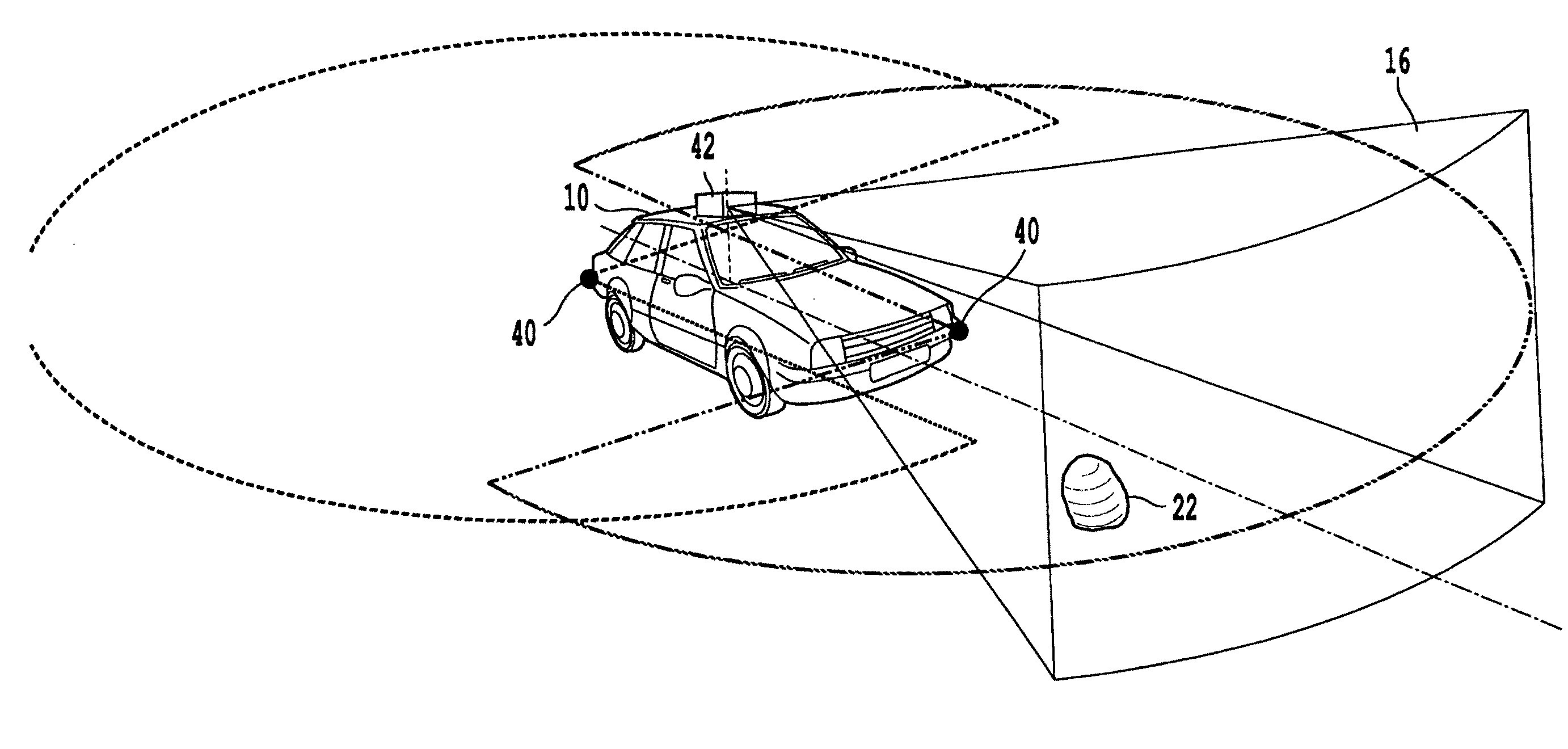
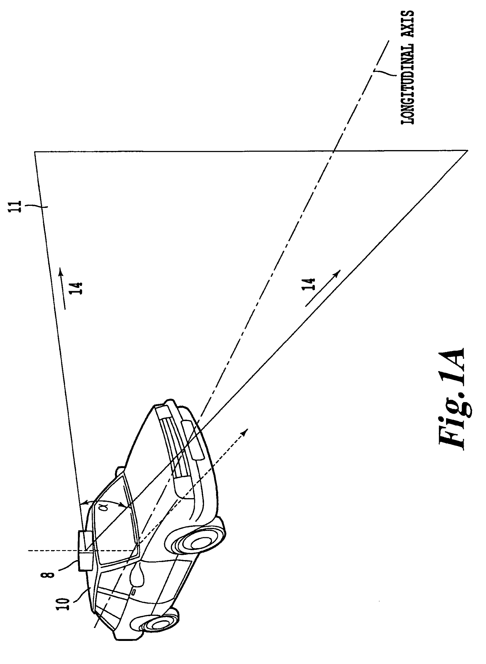
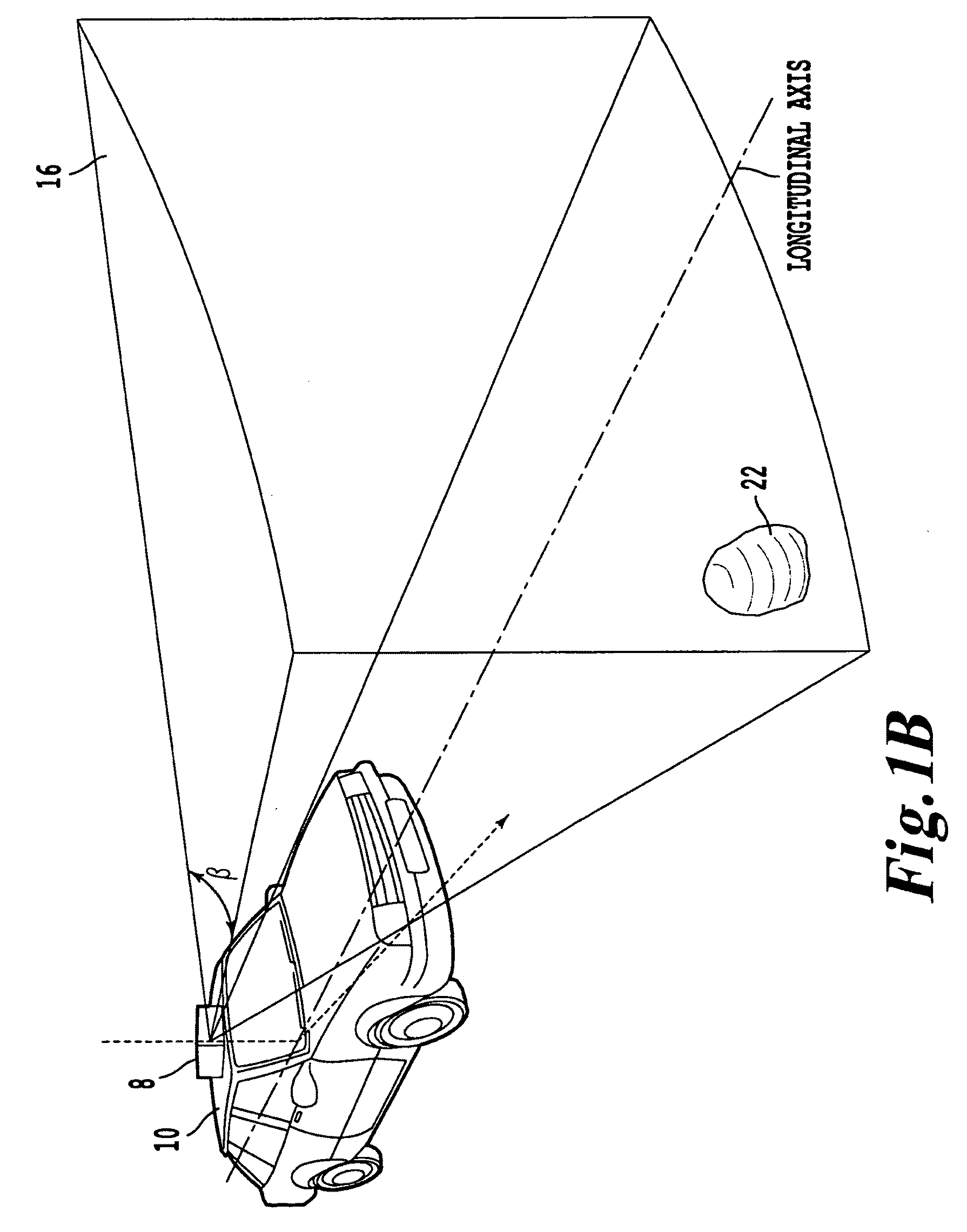
[0046]Referring now to the drawings, wherein like reference numerals designate identical, or corresponding parts throughout the several views, and more particularly to FIG. 1A, which depicts an imaging sensor 8 mounted, in one embodiment, on top of a vehicle 10 in which a two-dimensional (2D) scan is made in a sector of a plane 11 normal to a predetermined axis of the vehicle 10 referred to here for illustration purposes as a “vertical” scanning plane. This imaging sensor and its operation are described in more detail in U.S. Ser. No. 11 / 376,160. This imaging sensor is but one example an imaging sensor that can be used in the invention.

[0047]Nevertheless, the description here outlines briefly the operation of imaging sensor 8 in order to provide one context for application of the invention. The imaging sensor 8 includes in one embodiment an emitter 12 (as shown in FIG. 2) that transmits laser pulses (or light) 14 from the imaging sensor 8 into the environment about the vehicle 10. A...


PUM


Abstract

A navigation and control system including one or more position sensors configured to generate position signals indicative of the location and heading of a vehicle. The system includes one or more operation control mechanisms having inputs and producing outputs which control an operation of the vehicle and includes a self-contained autonomous controller disposed remote from the operation control mechanisms. The autonomous controller includes a processor configured to receive the position signals from the position sensors and to generate operation control signals defining an updated travel path for the vehicle, and a programmable interface providing communication among the position sensors, the operation control mechanisms, and the processor. The programmable interface is configured to normalize inputs to the processor from the position sensors and to generate compatible operation control signals applied as the inputs to the operation control mechanisms, whereby the self-contained autonomous controller is configurable for operation with a variety of different sensors and different operation control mechanisms.

Description

CROSS REFERENCE TO RELATED APPLICATIONS[0001]This application is related to U.S. Ser. No. 11 / 376,160, entitled “NAVIGATION AND CONTROL SYSTEM FOR AUTONOMOUS VEHICLES” filed Mar. 16, 2006 under Attorney Docket No. 284361US. The entire contents of this application are incorporated herein by reference.DISCUSSION OF THE BACKGROUND[0002]1. Field of the Invention[0003]The invention relates to an integrated sensor and computer-based algorithm system which controls and directs autonomously driven vehicles.[0004]2. Background of the Invention[0005]In a modern vehicle, the driver remains a critical component of the vehicle's control system as the driver makes numerous decisions directed to the safe operation of the vehicle including speed, steering, obstacle and hazard recognition, and avoidance thereof. Yet, the driver's ability to perform all of these functions can become compromised due to physical factors such as driver fatigue, driver impairment, driver inattention, or other factors such...

Claims


Application Information

Patent Timeline
Patent Type & Authority Applications(United States)
IPC IPC(8): G05D1/02G01S17/86G01S17/931
CPCG01S17/023G01S17/936G05D1/024G05D1/0246G05D1/027G05D1/0248G05D1/0278G05D2201/0213G05D1/0214G08G1/16G05D1/0274G01S17/86G01S17/931G05D1/0212
Inventor TREPAGNIER, PAUL GERARDNAGEL, JORGE EMILIODOONER, MATTHEW TAYLORDEWENTER, MICHAEL THOMASTRAFT, NEIL MICHAELDRAKUNOV, SERGEYKINNEY, POWELLLEE, AARON
Owner SAMSUNG ELECTRONICS CO LTD
Why Eureka
Try Eureka