Laser-welded crane rail for suspended crabs

Inactive Publication Date: 2010-05-06
STAHL CRANESYSTEMS GMBH
View PDF22 Cites 9 Cited by
  • Summary
  • Abstract
  • Description
  • Claims
  • Application Information

AI Technical Summary

Benefits of technology

[0005]In view of the foregoing, a general object of the present invention is t

Problems solved by technology

The welding costs are relatively high since, during the welding process, the parts must be correctly positioned and fixed in place by means of corresponding devices.
Furthermore, the welding seams are located where there is a risk o

Method used


Image

  • Laser-welded crane rail for suspended crabs
  • Laser-welded crane rail for suspended crabs
  • Laser-welded crane rail for suspended crabs

Examples


Embodiment Construction

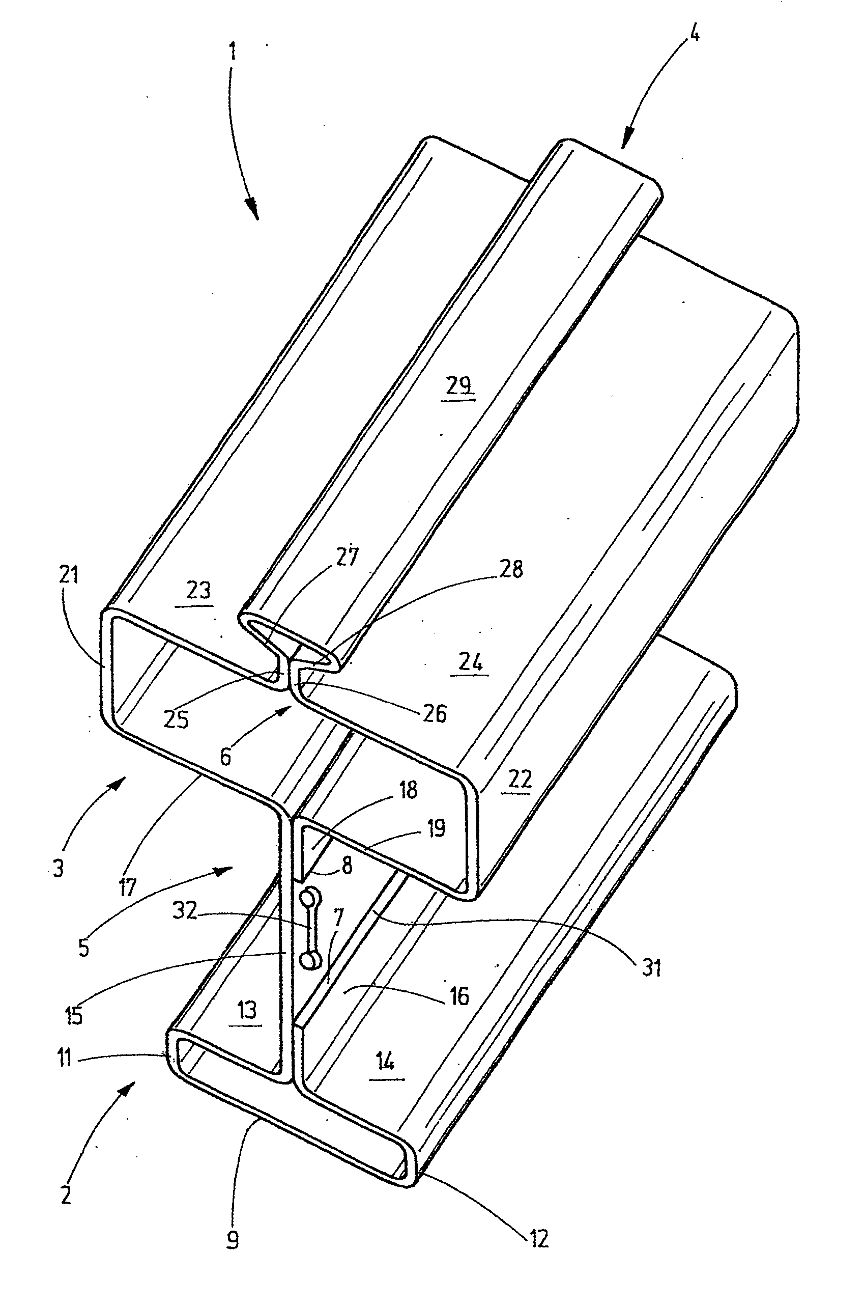
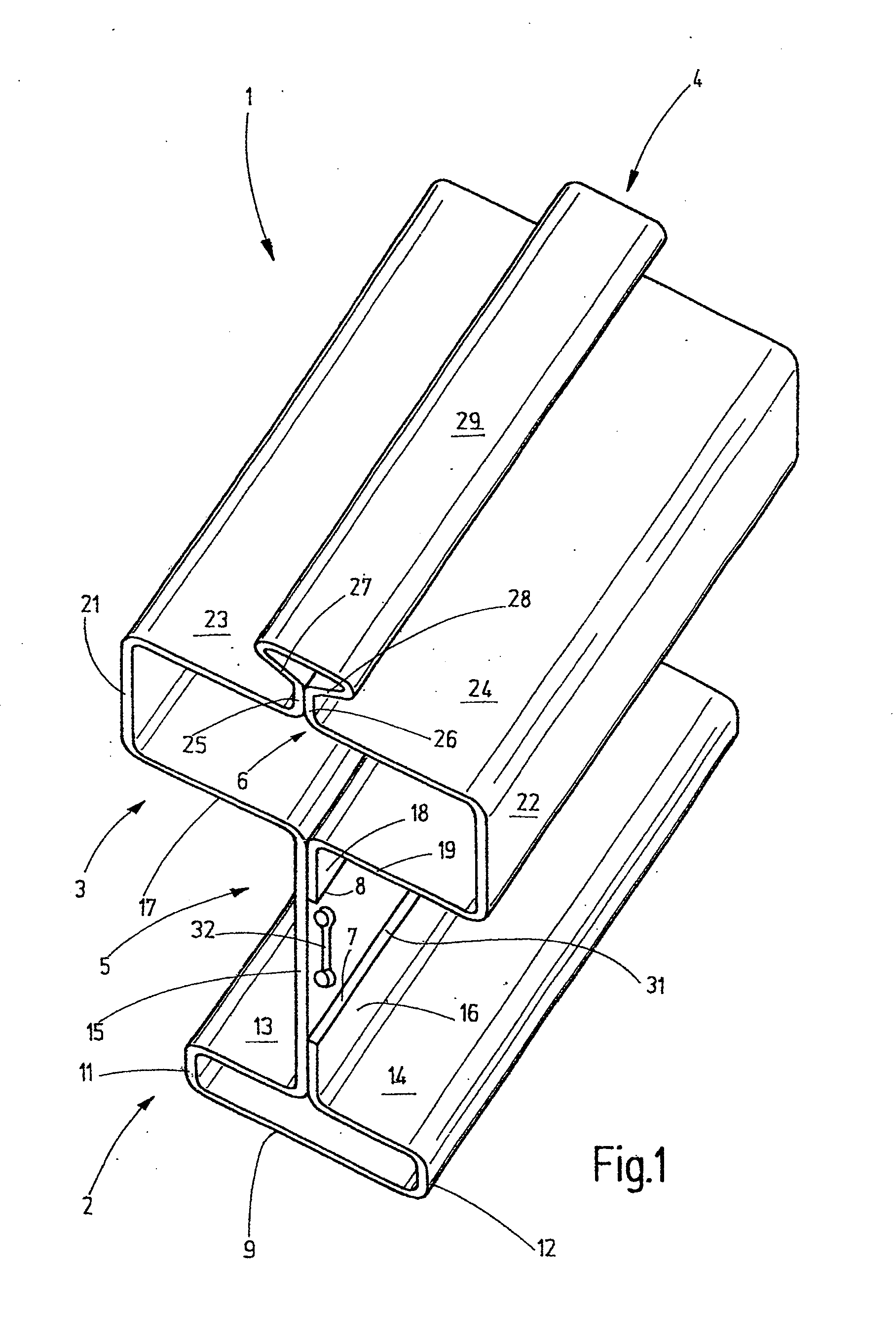
[0025]Referring to FIG. 1 of the drawings, a section of a crane rail 1 is shown in the operating position. The crane rail 1 is designed, in particular, in the form of a travel rail for suspended crabs, preferably suspended monorail crabs. The crane rail 1 features a bottom flange 2 in the form of a hollow profile, a top flange 3 that is also in the form of a hollow profile, as well as a support flange 4 that is again in the form of a hollow profile. The bottom flange 2 is connected to the top flange 3 by a web 5. The connection between the support flange 4 and the upper side of the top of flange 3 is produced with the aid of a web 6.

[0026]The crane rail 1 consists of an endless roll-formed sheet steel strip, the strip edges of which are designated by reference symbols 7 and 8. Due to the roll-forming, the hollow bottom flange 2 is includes a bottom wall 9 that transitions into side walls 11 and 12 at its edges. The bottom wall 9 is planar and extends horizontally in the operating st...


PUM


Abstract

Disclosed is a crane rail made from a roll-formed steel sheet strip. Said crane rail altogether comprises a top flange and a bottom flange. A support flange that has a triangular cross-section is additionally embodied on the top flange. The edges of the steel strip are laser-welded to the web.

Description

CROSS-REFERENCE TO RELATED APPLICATIONS[0001]This patent application is the national phase of PCT / EP2007 / 009684, filed Nov. 8, 2007, which claims the benefit of German Patent Application No. 102006054682.2, filed Nov. 17, 2006.FIELD OF THE INVENTION[0002]The present invention relates generally to crane rails for suspended crabs.BACKGROUND OF THE INVENTION[0003]Travel rails for suspended crabs are made from roll-formed sheet steel for cost and weight reasons. One example of such a travel rail is described in DE 41 19 868 A1. The rail forms a hollow bottom flange and a hollow top flange that are connected to one another by a web. The web is configured as a single piece with one-half of the hollow top flange and one-half of the hollow bottom flange situated thereunder. The other halves of the top flange and the bottom flange consist of two individual roll-formed sheets that are then correctly positioned and joined to the part containing the web. These parts are then welded together.[00...

Claims


Application Information

Patent Timeline
IPC IPC(8): E01B25/22B66C6/00F16M13/00
CPCE01B25/24B66C6/00
Inventor HESS, WILFRIED
Owner STAHL CRANESYSTEMS GMBH
Why Eureka
Try Eureka