Solar collector

a solar collector and solar energy technology, applied in the field of solar collectors, can solve the problems of limited flexibility of solar collectors for various applications, and achieve the effect of preventing fluid leakag

Active Publication Date: 2010-05-06
KINGSPAN HLDG (IRL) LTD
View PDF3 Cites 20 Cited by
  • Summary
  • Abstract
  • Description
  • Claims
  • Application Information

AI Technical Summary

Benefits of technology

[0035]In a preferred embodiment, the fluid connection means comprises a tubular opening adapted to sealingly engage a similar tubular opening on an adjacent elongate tube. Preferably said tubular open...

Problems solved by technology

The restrictive design of such traditional solar thermal collectors h...

Method used


Image

  • Solar collector
  • Solar collector
  • Solar collector

Examples


first embodiment

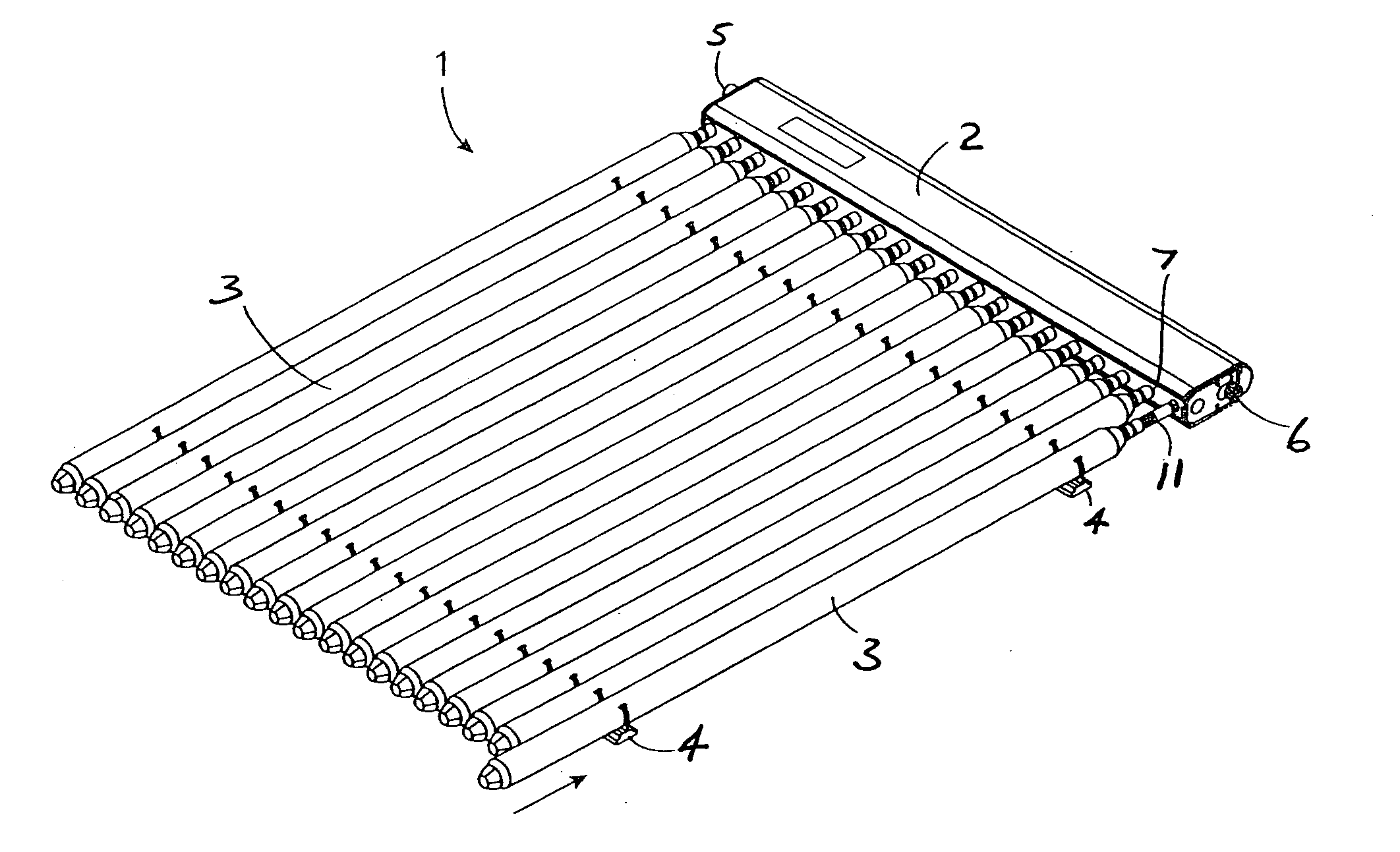
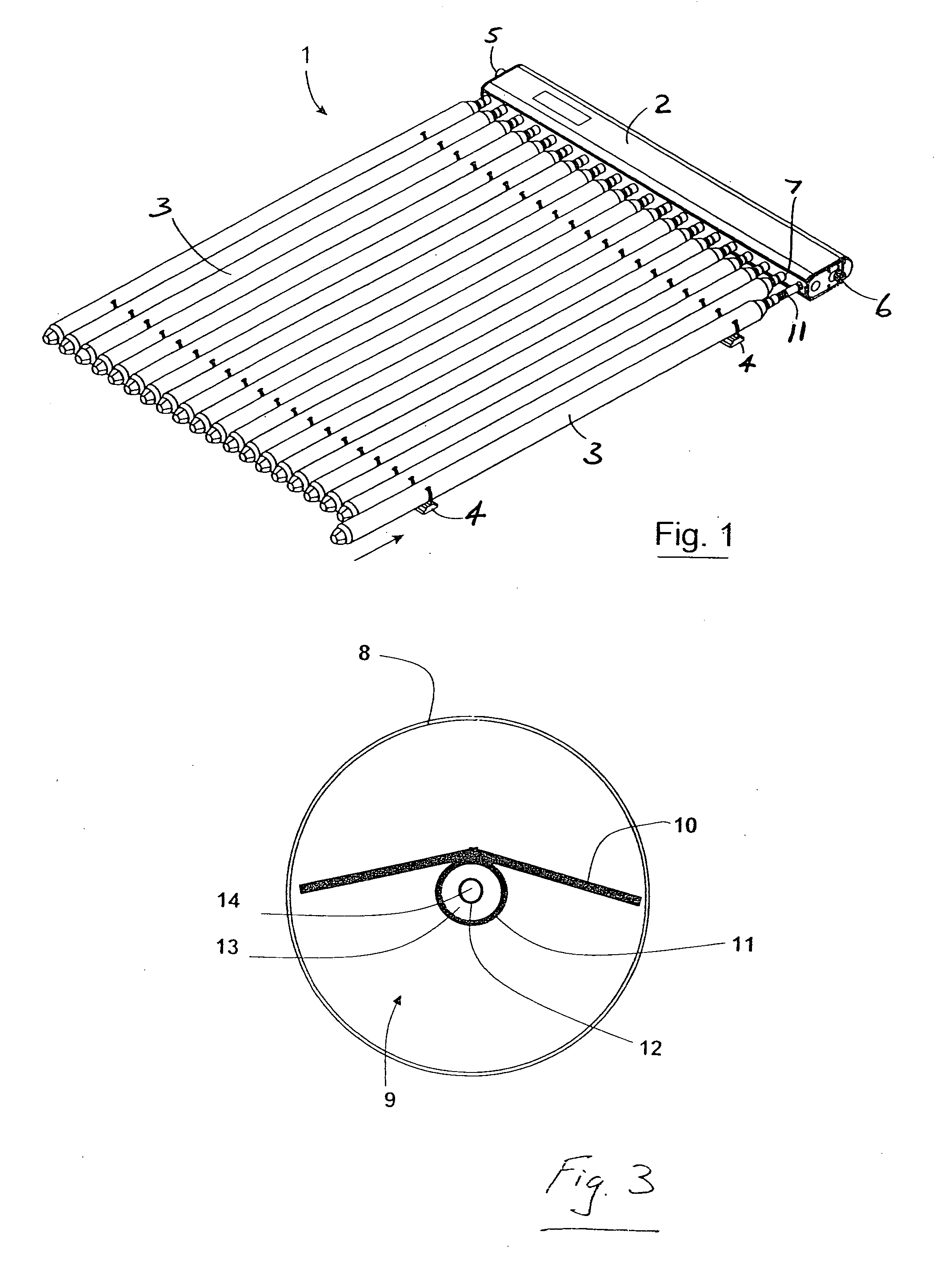
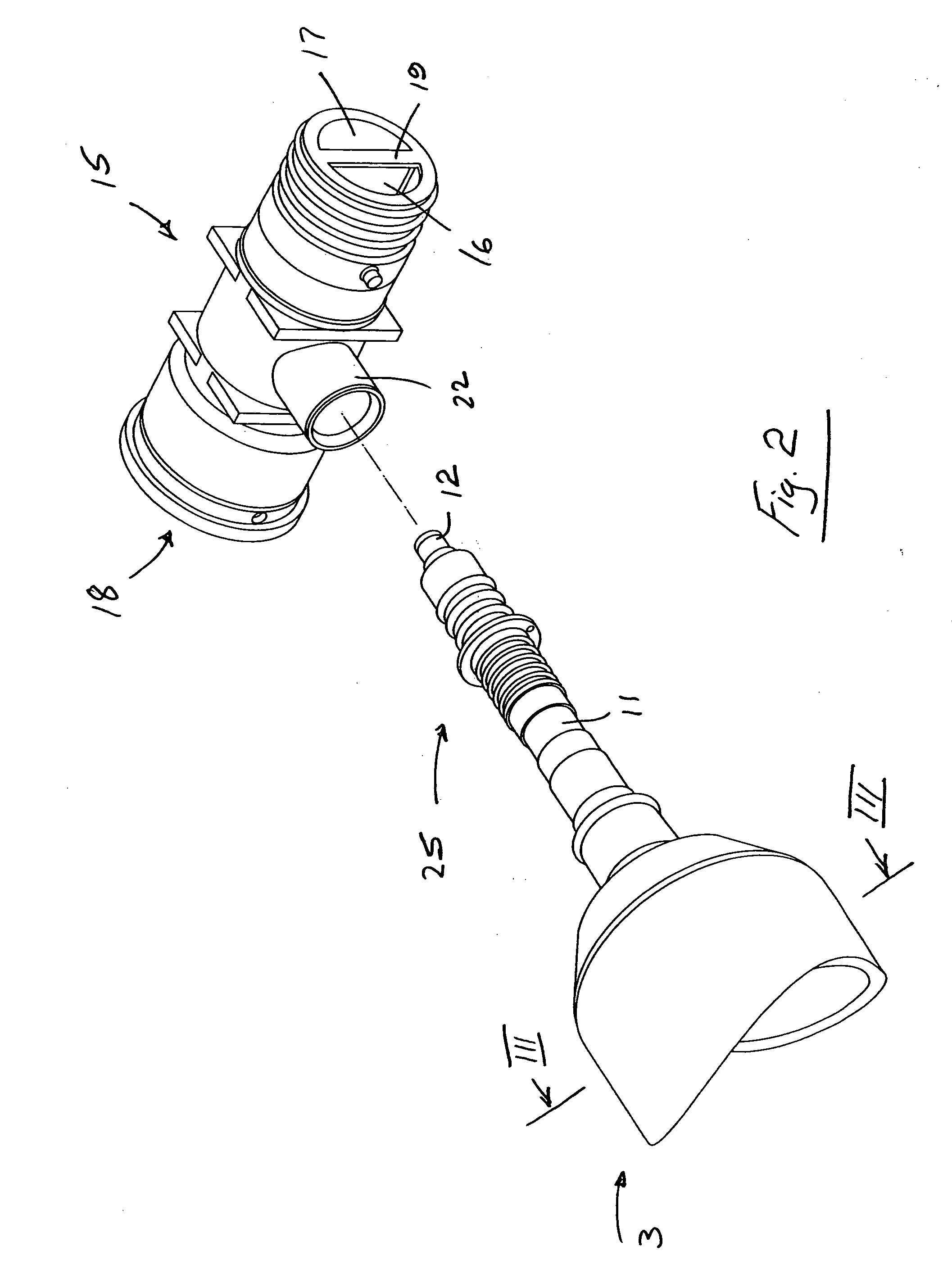
[0068]As illustrated in FIG. 2 to FIG. 28 a solar collector assembly according to the present invention of the direct flow type comprises a solar absorbing tube 3 comprising an evacuated radiation transparent enclosure 8 enclosing an absorbing section 9, comprising a radiation absorbing plate 10 for absorbing solar radiation and an elongate tube 1, containing a working fluid (heat transfer medium), in thermal contact with said radiation absorbing plate 10. The elongate tube 1 contains a concentrically positioned inner pipe 12 thereby forming two concentric internal flow passageways 13, 14 for the flow of a fluid to be heated. The elongate tube 1 extends out of one end of the solar absorbing tube 3 and into an end fitting 15 wherein an annular outer passageway 13 of the elongate tube 1 communicates with a cold fluid inlet conduit stream 16 within the end fitting 15 and the inner passageway 14 of the elongate tube 1 communicates with a hot fluid outlet conduit stream 17 within the end...

second embodiment

[0092]As illustrated in the FIG. 29 to FIG. 32, the invention for use with solar collectors of the heat-pipe type comprises an end fitting 15 provided with a tubular passage 18 provided with a pipe receiving portion 22 extending orthogonally to the tubular passage 18 modified for receiving the condenser 35 and the sealing plug 36 of a heat-pipe type solar collector tube 3.

[0093]Each heat tube solar tube 3 comprises an evacuated radiation transparent tube 8 enclosing a radiation absorbing plate 10 in thermal contact with an evaporator section 38 of a heat pipe 37, in thermal contact with said radiation absorbing plate 10. The evaporator section 38 is enclosed within the evacuated radiation transparent enclosure 8 to prevent heat loss. Each heat pipe solar tube 3 contains a suitable working fluid.

[0094]Each heat pipe includes a condenser section 35 at a distal end of the elongate tube 3 remote from the evaporator section 37, wherein the vaporised working fluid evaporated in the evapor...


PUM


Abstract

A solar collector comprises a solar absorbing tube 3 containing elongate tube 11 that extends out of one end of the solar absorbing tube 3 and into an end fitting 15 wherein an annular outer passageway 13 of the elongate tube 11 communicates with a cold fluid inlet conduit 16 within the end fitting 15 and the inner passageway 14 of the elongate tube 11 communicates with a hot water outlet conduit 17 within the end fitting 15. Each end fitting 15 is provided-with a receiving portion 22 extending orthogonally to the tubular passage 18 for receiving an end of the concentric elongated tube 11. The end fittings 15 are interconnected to provide fluid flow paths without the need for a manifold. Any number of solar collector tubes can be interconnected in this way. The invention also applies solar collectors of the heat pipe type.

Description

INTRODUCTION[0001]The invention relates to a solar collector for converting solar radiation into heat and to transfer the latter with the maximum possible efficiency to a fluid heat transferring means (e.g. water or air) whereby the heat can be utilised in a domestic or industrial application, for example to heat a domestic hot water or central heating system.[0002]A solar collector typically comprises a number of elongate tubes containing a radiation absorbing plate for absorbing solar radiation in contact with a pipe through which the fluid to be heated can be passed or within which is contained a working fluid for transferring heat to the fluid to be heated. The radiation absorbing plate and at least a portion of the pipe are enclosed within an evacuated radiation transparent enclosure to prevent heat loss.[0003]In one type of solar collector, known as the direct flow type, the fluid to be heated flows through the pipe in contact with the plate for direct conduction of heat betwe...

Claims


Application Information

Patent Timeline
IPC IPC(8): F24J2/24F24S10/40F24S10/70F24S10/95
CPCY02E10/44Y02B10/22F24S10/90F24S80/30F24S10/45F28D15/0275F24S10/95Y02B10/20
Inventor DAVIS, PATRICK ROBERTBAUER, BORISPELAN, RICHARDMCENTEE, PAUL THOMAS
Owner KINGSPAN HLDG (IRL) LTD
Why Eureka
Try Eureka