Impact Rapping Device

a technology of impact rapping and hammer, which is applied in the direction of portable percussive tools, combustion processes, combustion treatment, etc., can solve the problems of inapplicability of apparatuses, inability to locate in very limited spaces, and inability to choose the direction of hammer impact freely, so as to reduce the risk of damaging the hammer and the anvil, reduce the force and stress, and the effect of high spring constan

Active Publication Date: 2010-05-06
FOSTER WHEELER ENERGIA OY
View PDF10 Cites 16 Cited by
  • Summary
  • Abstract
  • Description
  • Claims
  • Application Information

AI Technical Summary

Benefits of technology

[0012]According to the present invention, the hammer is supported to lean on the anvil in such a way that the hammer can move only in one direction. This can be realized, for example, in such a way that one part of the anvil prevents movements of the hammer in other directions. In some special cases, when the assembly position of the rapping device is predetermined, it may be sufficient that the anvil supports the hammer only from below and from the sides. The structure of the anvil, in accordance with the invention, is preferably such that one of its parts prevents all possible transverse movements of the hammer, and, therefore, the anvil and the hammer of the rapping device are preferably arranged to move, at least partially, with each other.
[0022]The rapping device is simple in the structure and it may be preassembled in the manufacturing stage. This simplifies the assembly of the apparatus and decreases the costs of the apparatus, as well as the maintenance need thereof. The apparatus is a compact unit, which may be easily noise-shielded and assembled to any position needed. In practical applications, there is usually a large number of rapping devices, which can be completely separate or they may have, for example, a common pneumatic tensioning device, which guides the rapping pulses in a suitable sequence to a different rapping device. Owing to the small size and low weight, they can be assembled even to narrow spaces and, also, close to each other, if necessary.

Problems solved by technology

Such apparatuses are usually rather large and heavy, so they cannot be located in very limited spaces.
Additionally, the direction of the hammer impact cannot be chosen freely, so the apparatuses are not applicable, for example, for cleaning the lower sides of the inclined surfaces in funnel-shaped apparatuses.
The apparatuses are also noisy, and rather complicated to construct and to assemble, and they require a lot of maintenance.
The problem with this construction is that both the rapping device and the hammer arm have to be assembled very accurately, to have the impact directed precisely to the end of the hammer arm.
Furthermore, the thermal motion of the heat exchange tubes can change the position of the hammer arm in such a way that the impact hits the surface eccentrically or inclined, which, again, may cause, for example, the hammer arm to come loose from the heat exchange tubes.
This arrangement may have a problem that the connecting element is too rigid, and transfers vibration, whereby, the guiding device of the solenoid can be damaged and / or that the connecting element is too flexible, whereby the impact may be inclined, which, again, may damage the magnetic core, the hammer arm or the joint between the surface to be rapped and the hammer arm.

Method used


Image

  • Impact Rapping Device
  • Impact Rapping Device
  • Impact Rapping Device

Examples


Embodiment Construction

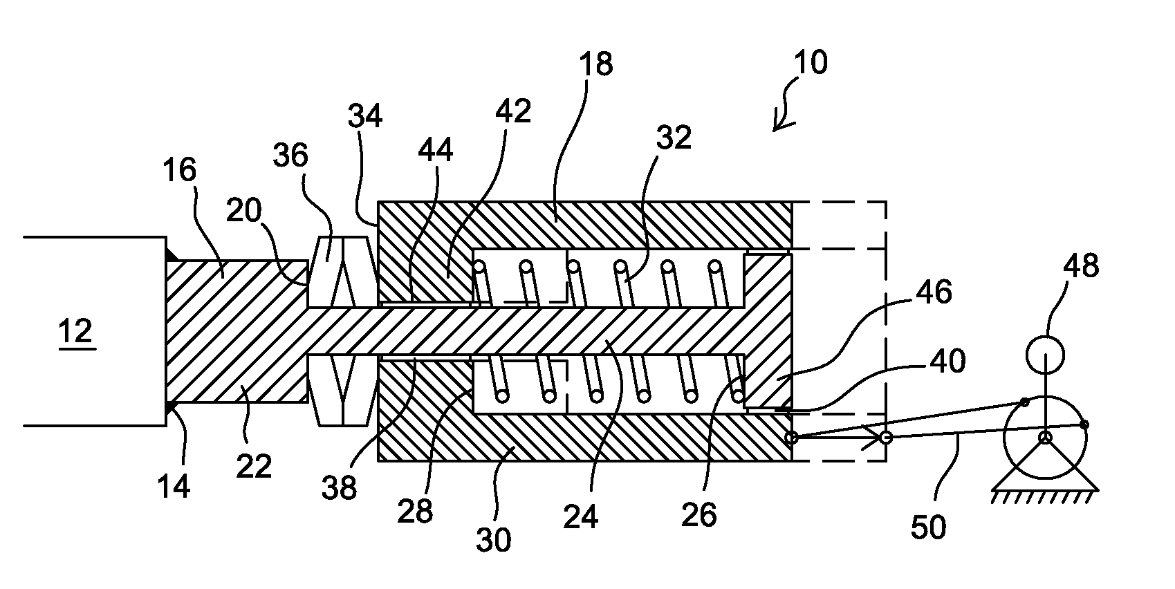
[0025]FIG. 1 illustrates a rapping device 10, in accordance with a preferred embodiment of the present invention, comprising an anvil 16 attached by means of a welded seam 14 to a hammering beam 12 and a hammer 18 connected to the anvil 16. If the wall to be rapped is, for example, an outer wall of a reactor, channel or funnel, one end of the hammering beam 12, (not shown in FIG. 1), may be welded to the wall. Alternatively, in such a case, a separate hammering beam 12 is not necessary, but the anvil 16 may be connected directly to the wall to be rapped. If, in turn, there are, for example, heat exchange tube banks in the gas-tight space of a reactor or a steam boiler are to be rapped, the hammering beam 12 may be flexibly sealed to the wall of the gas space and welded to the heat exchange tubes or their connecting piece. Since the different sealing and attaching methods of the hammering beam 12 are of a known technique, they will not be described below in detail.

[0026]The anvil 16 ...


PUM

PropertyMeasurementUnit
weightaaaaaaaaaa
lengthaaaaaaaaaa
lengthaaaaaaaaaa

Abstract

An impact rapping device includes a stationary anvil integrated with a surface to be rapped, the anvil having a hammering axis perpendicular to the surface to rapped, a hammer arranged to move coaxially with the hammering axis, to hit an impact surface of the anvil, and a device for moving the hammer. The anvil and the hammer form a compact unit, which can be assembled in any position. The hammer is supported to lean on the anvil in such a way that the position of the hammer automatically follows changes of place or position of the anvil, and so that the hammer can move only parallel to the hammering axis.

Description

[0001]This application is a U.S. national stage application of PCT International Application No. PCT / FI2007 / 050688, filed Dec. 13, 2007, published as PCT Publication No. WO 2008 / 071852 A1, on Jun. 19, 2008, and which claims priority from Finnish patent application number FI-20065801, filed Dec. 14, 2006.FIELD OF THE INVENTION[0002]The present invention relates to an impact rapping device, being applicable, for example, for removing fouling from heat sources, plate-structured funnels or channels of steam boilers, or heat recovery tubes for pyrometallurgical processes. Thus, the invention especially relates to an apparatus comprising a stationary anvil integrated with the surface to be rapped, the anvil having a hammering axis perpendicular to the surface to be rapped, a hammer, arranged to move coaxially with the hammering axis to hit an impact surface of the anvil, and a device for moving the hammer.[0003]The fouling of surfaces can disturb the operation of the plant in question, in...

Claims


Application Information

Patent Timeline
Patent Type & Authority Applications(United States)
IPC IPC(8): F28G7/00B08B7/02
CPCB25D11/12F28G7/00B08B7/02B25D11/064B25D2250/371Y10T29/4583F23J3/02
Inventor PEIPPO, RAUNO
Owner FOSTER WHEELER ENERGIA OY
Why Eureka
Try Eureka