
Fuel supply and combustion chamber systems for fastener-driving tools

a technology of fastener-driving tools and fuel supply, which is applied in the direction of packaging, nailing tools, liquid transfer devices, etc., can solve the problems that portable power tools do exhibit some operational drawbacks or limitations, and achieve the effect of increasing the total volumetric capacity of multiple combustion chambers, facilitating speed of operation, and reducing the number of power tools

Active Publication Date: 2010-05-06
ILLINOIS TOOL WORKS INC
View PDF35 Cites 32 Cited by
  • Summary
  • Abstract
  • Description
  • Claims
  • Application Information

AI Technical Summary

Benefits of technology

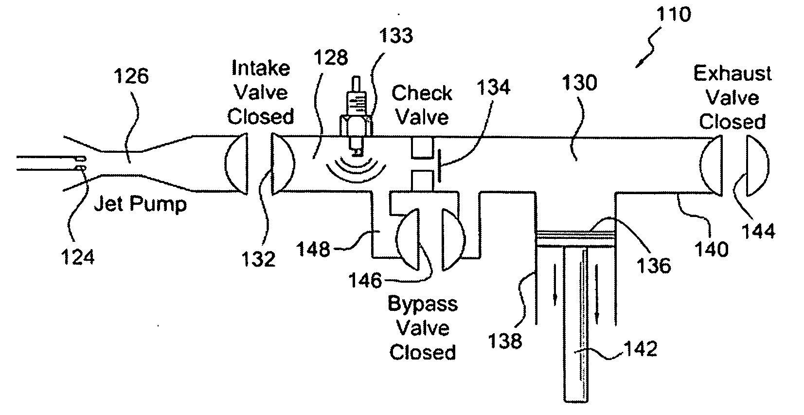
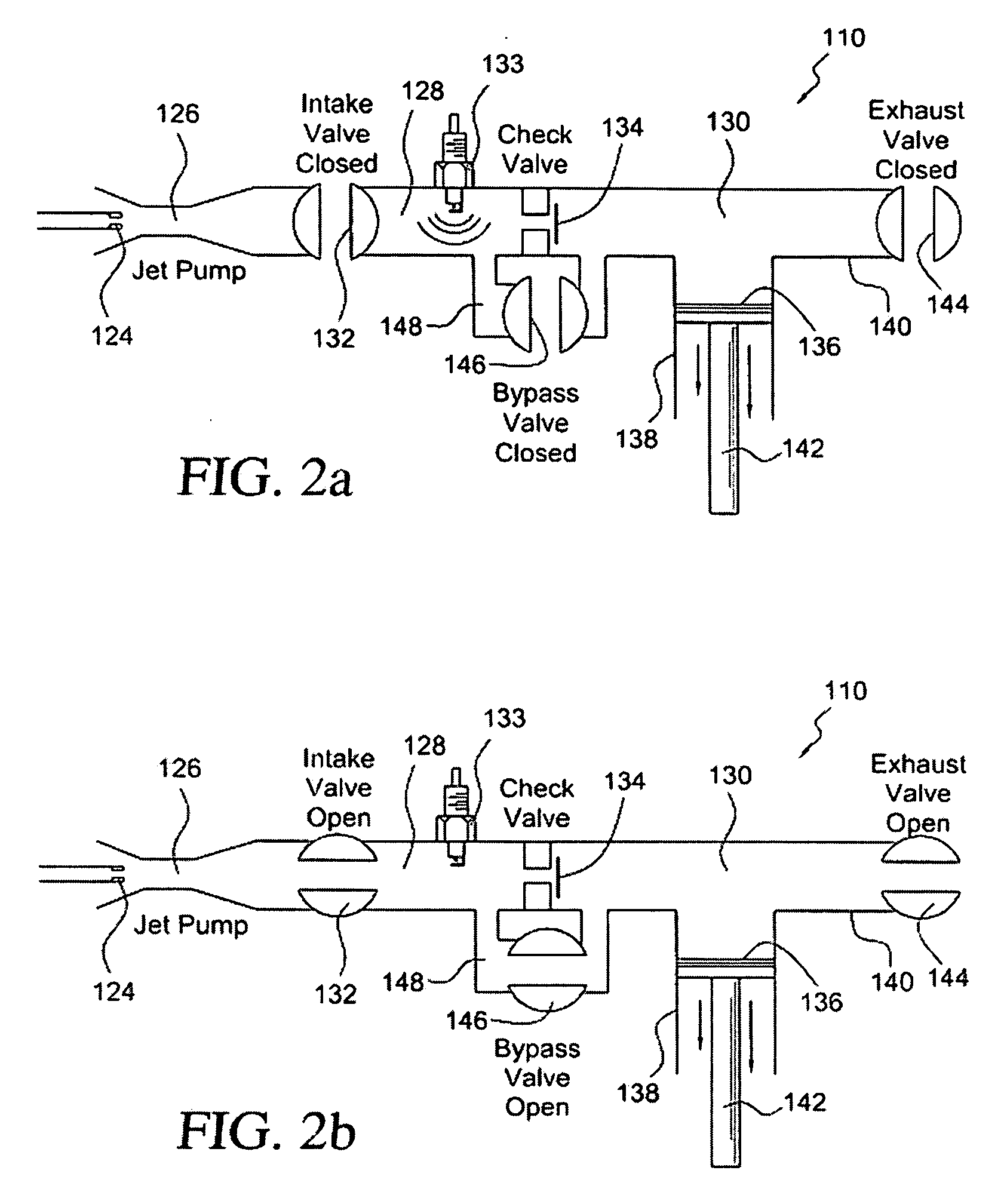
[0007]In accordance with additional principles and teachings of the present invention, there is provided a second embodiment of a new and improved fuel supply and combustion chamber system for a portable power tool which comprises the use of multiple combustion chambers for achieving predetermined combustion and power output characteristics or parameters, wherein the same comprises, for example, a first precombustion chamber and a second main combustion chamber, a bypass valve interposed between and fluidically connecting the first and second combustion chambers together under exhaust gas scavenging or purging conditions, and a jet pump disposed upstream of the first pre-combustion chamber for admitting a predetermined charge or amount of fuel into the first pre-combustion chamber and for inducing or entraining air into the predetermined charge or amount of fuel for mixing therewith in order to form an air-fuel mixture having a predetermined stoichiometric ratio. A check valve is operatively associated with an orifice so as to control the fluidic communication between the first pre-combustion chamber and the second main combustion chamber, or alternatively, in accordance with the principles and teachings of a first modified embodiment of the second embodiment of the new and improved fuel supply and combustion chamber system for a portable vapor tool, the check valve may effectively be eliminated thereby permitting constant or permanent communication between the first pre-combustion chamber and the second main combustion chamber.
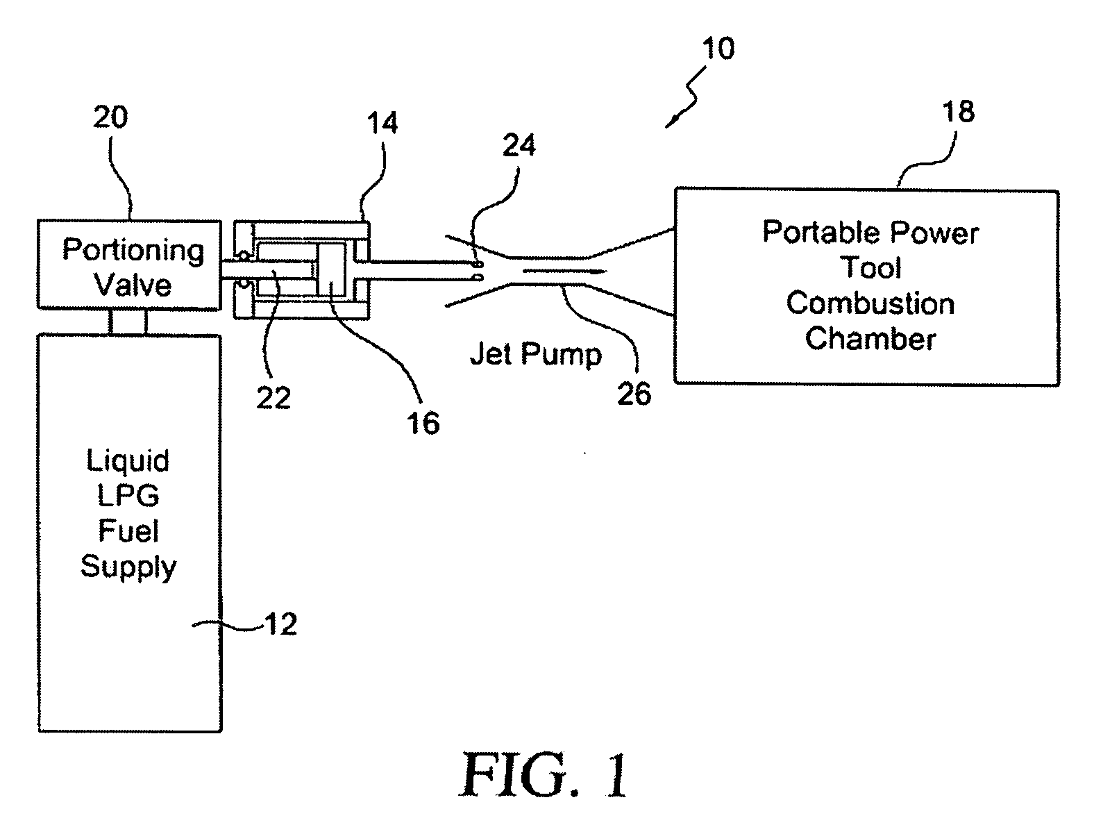
[0008]In this manner, greater air-fuel mixture ratios are permitted, and the total volumetric capacity of the multiple combustion chambers is effectively increased thereby advantageously affecting the vacuum volume and return stroke characteristics of the tool upon completion of a fastener firing cycle. Continuing still further, in accordance with the principles and teachings of second and third modified embodiments of the second embodiment of the new and improved fuel supply and combustion chamber system for a portable power tool, while both the first pre-combustion chamber and the second main combustion chamber are fluidically connected together by means of the aforenoted check valve or simply by means of one or more orifices, the bypass valve is effectively eliminated and the first pre-combustion chamber and the second main combustion chamber are respectively provided with separate fuel supplies, separate intake valves, and separate exhaust valves. This arrangement permits advantageous speed of operation, enhanced pressure conditions, and reduced downstream resistance to be developed within the power tool. In accordance with still additional principles and teachings of the present invention, there is provided a third embodiment of a new and improved fuel supply and combustion chamber system for a portable power tool which comprises the use of a gaseous liquid petroleum gas fuel supply as the fuel source for the portable power tool, and a portioning valve interposed between the gaseous liquid petroleum gas fuel supply and a jet pump disposed upstream of the portable power tool combustion chamber. In this manner, a predetermined portion or amount of the gaseous liquid petroleum gas fuel is supplied from the gaseous liquid petroleum gas fuel supply to the jet pump and into the combustion chamber of the power tool. Alternatively, in accordance with a fourth embodiment of the present invention, a metering valve may be utilized for supplying the gaseous liquid petroleum gas fuel toward the jet pump and the combustion chamber of the power tool, and an electrically timed pulse supply controller is operatively associated with the metering valve for effectively converting the same from a metering valve, for determining the flow rate of the fuel passing therethrough, to a portioning valve for determining the amount of the fuel passing therethrough.

Problems solved by technology

While the portable power tools, as exemplified by means of the portable power tool disclosed within the Veldman patent, are generally satisfactory, it is noted that such portable power tools nevertheless do exhibit some operational drawbacks or limitations.
Still yet further, portable power tools such as those disclosed within Veldman are not concerned with multiple combustion chamber systems which are desired or required for achieving predetermined combustion and power output characteristics or parameters.

Method used


Image

  • Fuel supply and combustion chamber systems for fastener-driving tools
  • Fuel supply and combustion chamber systems for fastener-driving tools
  • Fuel supply and combustion chamber systems for fastener-driving tools

Examples


second embodiment

[0023]More particularly, in connection with the operation of the second embodiment fuel supply and combustion chamber system 110 for a portable power tool, when an ignition, firing, and combustion operational cycle of the portable power tool is to be initiated, the first intake valve 132, the second exhaust valve 144, and the third bypass valve 146 are initially disposed at their OPEN positions, as illustrated within FIG. 2b, so as to admit or charge a predetermined stoichiometric air-fuel mixture into the pre-combustion and main combustion chambers 128,130 from the jet pump 126, and subsequently, the first intake valve 132, the second exhaust valve 144, and the third bypass valve 146 are simultaneously moved to their CLOSED positions, as illustrated within FIG. 2a, in order to effectively entrap the air-fuel mixture within the pre-combustion and main combustion chambers 128,130. Subsequently, still further, ignition of the air-fuel mixture within the first primary combustion chambe...

first modified embodiment

[0028]With reference now being made to FIGS. 5a and 5b, the second embodiment of the new and improved fuel supply and combustion chamber system for the portable power tool 110, as illustrated within FIGS. 2a and 2b, is disclosed and is generally indicated by the reference character 510. It is noted that, in connection with the detailed description of this first modified embodiment of the second embodiment fuel supply and combustion chamber system for the portable power tool 510, the description will focus upon the particular structure characteristic of this first modified embodiment of the second embodiment fuel supply and combustion chamber system 510 and how the same differs from that of the second embodiment of the new and improved fuel supply and combustion chamber system for the portable power tool 110 as illustrated within FIGS. 2a and 2b. In addition, it is also noted that the structural components of this first modified embodiment of the second embodiment fuel supply and com...

second modified embodiment

[0030]Turning now to FIG. 6, the second embodiment of the new and improved fuel supply and combustion chamber system for the portable power tool 110, as illustrated within FIGS. 2a and 2b, is disclosed and is generally indicated by the reference character 610. It is noted that, in connection with the detailed description of this second modified embodiment of the second embodiment fuel supply and combustion chamber system 110 for the portable power tool, the description will focus upon the particular structure characteristic of this second modified embodiment of the second embodiment fuel supply and combustion chamber system 610 and how the same differs from that of the second embodiment of the new and improved fuel supply and combustion chamber system for the portable power tool 110 as illustrated within FIGS. 2a and 2b. In addition, it is also noted that the structural components of this second modified embodiment of the second embodiment fuel supply and combustion chamber system 6...


PUM


Abstract

A fuel supply and combustion chamber system for a portable power tool, such as, for example, a fastener-driving tool, wherein the fuel supply and combustion chamber system can utilize liquid or gaseous fuels. The fuel supply and combustion chamber system can comprise multiple combustion chambers for achieving predetermined combustion and power output characteristics. In addition, the fuel supply and combustion chamber system can utilize portioning valve structures for providing predetermined amounts of either a gaseous or liquid fuel into the portable power tool combustion chamber.

Description

CROSS-REFERENCE OF RELATED PATENT APPLICATION[0001]This patent application is a Continuation-in-Part of United States patent application entitled FUEL SUPPLY AND COMBUSTION CHAMBER SYSTEMS FOR FASTENER-DRIVING TOOLS which was filed on May 14, 2008 and which has been assigned Ser. No. 12 / 084,963.FIELD OF THE INVENTION[0002]The present invention relates generally to portable power tools, and more particularly to new and improved fuel supply and combustion chamber systems for such portable power tools, such as, for example, fastener-driving tools.BACKGROUND OF THE INVENTION[0003]Portable power tools having various different means for conducting or charging a combustible fuel into a suitable combustion chamber are of course well-known. An example of such a portable power tool is disclosed within U.S. Pat. No. 4,905,634 which issued to Veldman on Mar. 6, 1990. In accordance with the particular structure comprising the portable power tool of Veldman, the portable power tool disclosed ther...

Claims


Application Information

Patent Timeline
Patent Type & Authority Applications(United States)
IPC IPC(8): B25C1/08B67D5/06
CPCB25C1/08
Inventor ADAMS, JOSEPH S.
Owner ILLINOIS TOOL WORKS INC
Learn More