Integration system for lifting surfaces semi-parts in aircrafts

a technology for aircrafts and semi-parts, which is applied in the direction of fuselages, transportation and packaging, and splits/stringers, etc. it can solve the problems of increasing the weight of the structure, reducing the structural efficiency of the zone in the vicinity, and affecting so as to save economic resources, simplify the design, manufacture and assembly of components, and maintain the structural efficiency of the array

Active Publication Date: 2010-05-06
AIRBUS OPERATIONS SL
View PDF5 Cites 4 Cited by
  • Summary
  • Abstract
  • Description
  • Claims
  • Application Information

AI Technical Summary

Benefits of technology

[0015]The invention solves the problem of accessibility in the final integration of the semi-boxes maintaining the structural efficiency of the array and simplifying the design, manufacture and assembly of components, with the consequent final saving in economic resources. Furthermore, by means of the invention it is possible to introduce a large number of bars, since the number of attachment points is reduced, increasing the resistance and rigidity of the ensemble. Moreover, the design of the invention permits the load between bars to be transmitted directly without any need to load the corresponding metal support or frame, thereby reducing undesirable bending effects concentrated in it. Other advantages of the invention consist of the fact that for the assembly it is not necessary to make and that the number of inspections necessary over the life of the aircraft for corrosion reasons is minimized. It can be concluded that the main advantage of the invention lies in the fact that using bars in a manner of a lattice as attachment system for boxes significantly reduce the number of inspection openings necessary for its assembly.

Problems solved by technology

Said inspection openings imply an appreciable reduction in the structural efficiency of the zones in their vicinity.
From the viewpoint of the design, manufacture and assembly, each inspection opening or the capacity to dismantle an element implies a major complication.
Moreover, each inspection opening implies an increase in the weight of the structure.The size of the lifting surface is sufficiently small to allow access to assembly operations from the outside.

Method used


Image

  • Integration system for lifting surfaces semi-parts in aircrafts
  • Integration system for lifting surfaces semi-parts in aircrafts
  • Integration system for lifting surfaces semi-parts in aircrafts

Examples


Embodiment Construction

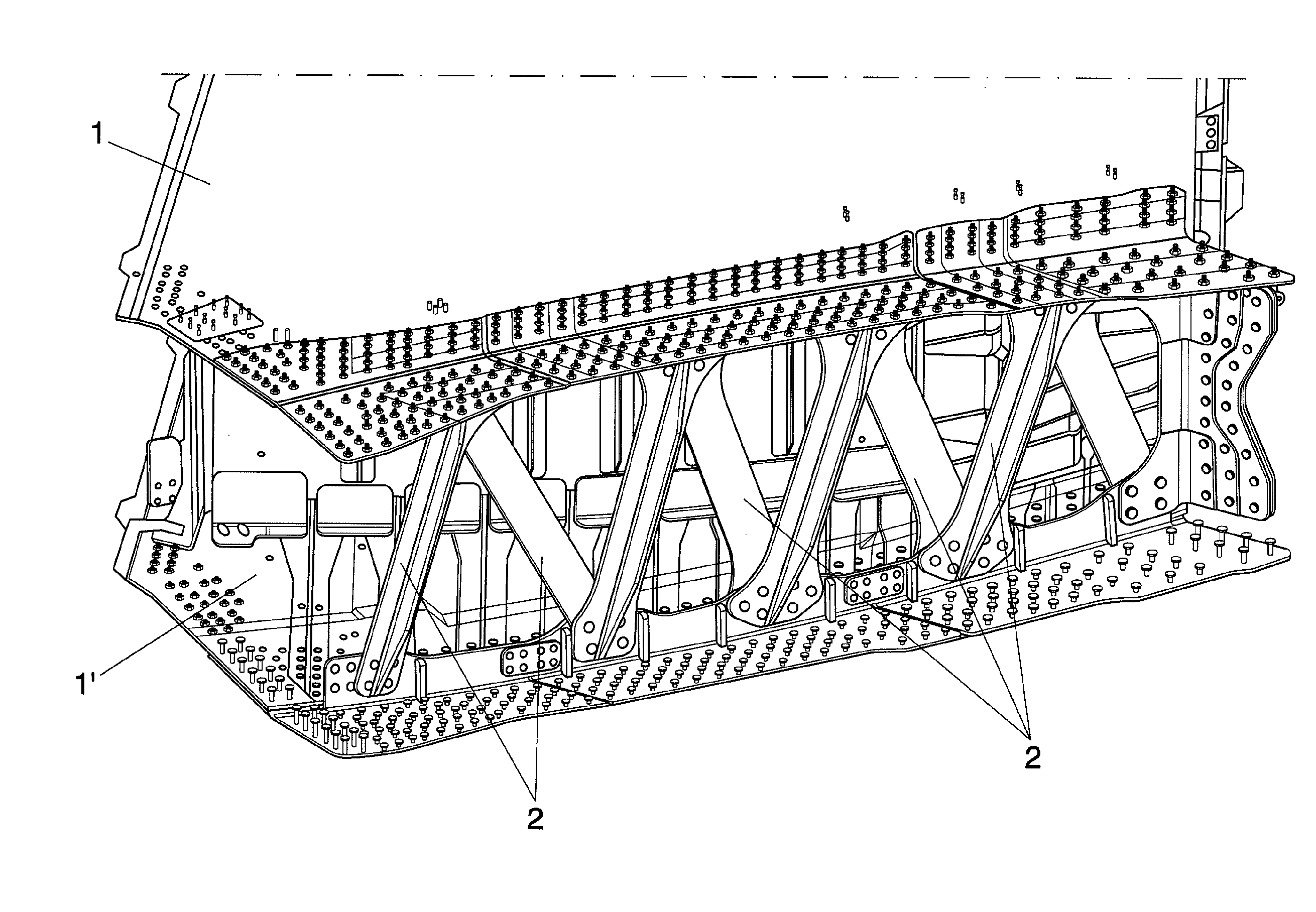
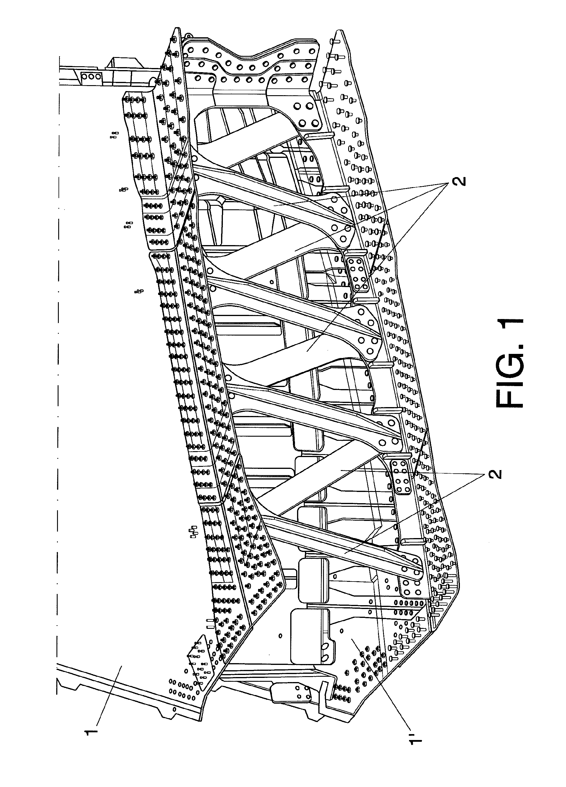
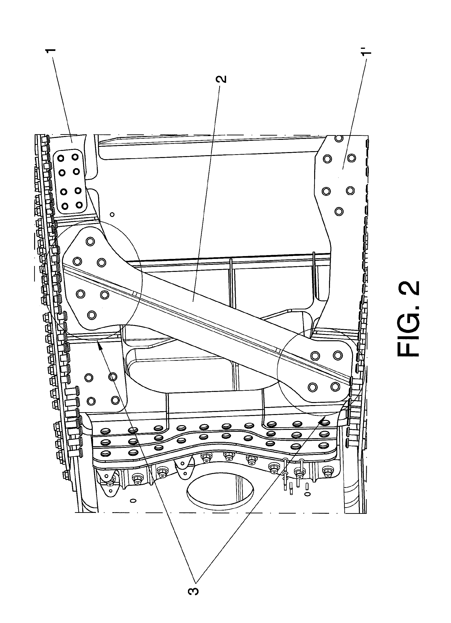
[0009]In order to achieve the objectives stated above, the invention consists of an integration system of lifting surfaces semi-parts in aircrafts, where the lifting surface consists of a torsion box capable of bearing aerodynamic and inertial loads, and the semi-parts comprising it are connected together with means of attachment which conventionally consist of a rib in one piece in its plane of symmetry, the final assembly of said lifting surfaces requiring some inspection openings or holes for being able to gain access to the corresponding attachments.

[0010]As a novelty, according to the invention, the means of attachment consist of an array or plurality of bars arranged in modular fashion in the manner of a lattice, such that the necessary number of said inspection openings is reduced and a sequential assembly connecting the upper and lower ends of the bars is facilitated.

[0011]According to the preferred embodiment of the invention, the bars present certain longitudinal ends with...


PUM


Abstract

The lifting surface consists of a torsion box capable of bearing aerodynamic and inertial loads, and the semi-parts (1, 1′) comprising it are connected together with joining means conventionally consisting of a rib in one piece in its plane of symmetry, the final assembly of said lifting surfaces requiring some inspection openings or holes for being able to gain access to the corresponding joints. The invention provides other joining means which avoid that rib and which consist of a plurality of bars (2) modularly arranged in the manner of a lattice, in such a is way that the required amount of said inspection holes is reduced, and a sequential assembly connecting the upper and lower ends of the bars (2) is facilitated.

Description

OBJECT OF THE INVENTION[0001]As stated in the title of this descriptive specification, the present invention relates to an integration system for semi-parts of lifting surfaces in aircrafts, the aim of which consists of providing a new system of attachment of boxes in the plane of symmetry of the lifting surfaces of airplanes or aircrafts. This is a design solution allowing the assembly of boxes without any need to make inspection openings or holes for accessibility in certain linings.[0002]The invention comes within the technical sector of aeronautics, and specifically to the assembly of the semi-parts making up a lifting surface in airplanes or aircrafts; being the basic aim of the invention to reduce the amount is of inspection openings or holes necessary for assembly, maintenance and revision operations.[0003]By means of the invention, problems of accessibility in the final integration of the semi-boxes are solved, maintaining the structural efficiency of the array and simplifyi...

Claims


Application Information

Patent Timeline
Patent Type & Authority Applications(United States)
IPC IPC(8): B64C3/18B64C3/22
CPCB64C3/18
Inventor LOBO BARROS, ABELBAJO GONZALEZ, JESUS VICENTELOZANO GARCIA, JOSE LUISPINTOR ARCHILLA, ANTONIO FRANCISCORODRIGUEZ BODAS, JESUS
Owner AIRBUS OPERATIONS SL
Why Eureka
Try Eureka