Hydraulic vehicle brake system and method for its operation

a technology of vehicle brakes and hydraulic brakes, applied in the direction of braking systems, mechanical equipment, transportation and packaging, etc., can solve the problems of wear compensation, inability to automatically operate, and inability to transfer electronic wheel brakes, etc., to achieve less expensive, reduce actuation energy and actuation power, and increase manufacturing complexity

Inactive Publication Date: 2010-05-06
ROBERT BOSCH GMBH
View PDF15 Cites 7 Cited by
  • Summary
  • Abstract
  • Description
  • Claims
  • Application Information

AI Technical Summary

Benefits of technology

[0006]One advantage of the invention is that the vehicle brake system is less expensive than a vehicle brake system whose wheel brakes are all self-amplifying, since self-amplifying wheel brakes—because of the greater manufacturing complexity due to the presence of the additional self-amplification device—are more expensive than conventional wheel brakes without self-amplification. If a self-amplifying wheel brake communicates with a wheel brake without self-amplification, then the self-amplification also acts on the wheel brake without self-amplification. If the self-amplifying wheel brakes are embodied with a powerful self-amplification, then all of the wheel brakes of the vehicle brake system according to the invention are able to achieve a self-amplification that corresponds to the self-amplification of a vehicle brake system whose wheel brakes are all self-amplifying, but have a less powerful self-amplification. Despite the use of wheel brakes without self-amplification, the self-amplification of the vehicle brake system according to the invention can be as powerful as the self-amplification of a vehicle brake system in which all of the wheel brakes are self-amplifying.
[0007]Another advantage of the invention is a lower actuation energy and actuation power than vehicle brake systems without self-amplification.
[0008]Advantageous embodiments and modifications of the invention disclosed in claim 1 are the subject of the dependent claims. According to claim 3, the self-amplifying wheel brakes have a different spring rate than the wheel brakes without self-amplification; preferably, the self-amplifying wheel brakes have a higher spring rate than the wheel brakes without self-amplification (claim 4). The wheel brakes of the wheels of the front axle can have the higher spring rate, which is only a difference if the self-amplifying wheel brakes are not provided on the wheels of the front axle, but instead on the wheels of the rear axle. The wheel brakes, i.e. the brake caliper and friction brake lining in a disc brake, are not absolutely rigid, but are instead deformed by the clamping force; the brake caliper is expanded and the friction brake lining is compressed. The actual advancing or clamping distance by which the brake piston is moved during an application of the brakes therefore increases. The ratio between the clamping force and the clamping distance yields the spring rate. A higher spring rate means a stiffer brake and a shorter clamping distance of the brake piston in order to produce a certain clamping force. The different spring rates of the brake calipers and the wheel brakes of the wheels of the front and rear axle, or more precisely stated, of the self-amplifying wheel brakes and the wheel brakes without self-amplification, can be used to influence a pedal force / pedal travel characteristic curve of the vehicle brake system. The goal is to approximate a characteristic curve of the kind to which a driver is accustomed in conventional hydraulic vehicle brake systems, for example with vacuum brake boosters and without self-amplifying wheel brakes. This familiar characteristic curve can be at least approximately achieved by selecting appropriate spring rates of the self-amplifying wheel brakes and of the wheel brakes without self-amplification and also by selecting an appropriate self-amplification intensity. In addition, with this embodiment of the invention, it is possible to keep the dependence of the pedal force / pedal travel characteristic curve to a minimum, particularly in the event of a change in a brake lining friction coefficient between the friction brake lining and the brake disc.
[0009]In an embodiment of the invention proposed according to claim 6, the vehicle brake system has no brake boosters, e.g. no vacuum brake boosters, and also has no separate vacuum pump. The elimination of these units is an advantage in terms of cost and space. The brake boosting is provided by the self-amplifying action of the self-amplifying wheel brakes and by the ratio of the piston areas of a master brake cylinder and the brake pistons of the wheel brakes.
[0010]The self-amplification devices of the self-amplifying wheel brakes can essentially be embodied in any form, i.e. in addition to being mechanical, they can also be hydraulic, for example. Claim 7 provides a mechanical self-amplification device with a wedge mechanism, whose meaning should also be understood to include a ramp mechanism with a wedge angle that changes over the length of the shifting distance of the friction brake lining. For a self-amplification in both driving directions, the wedge mechanism can have a counterpart wedge surface with an opposite slope.
[0011]According to claim 9, the self-amplifying friction brakes are travel-amplifying. In this instance, the movement of the friction brake lining in the circumference direction of the rotating brake disc shortens the clamping distance of the brake piston. Through a higher hydraulic force conversion ratio, i.e. a smaller piston area of the master brake cylinder in comparison to the piston areas of the brake pistons of the wheel brakes, it is possible to achieve a powerful amplifying action using travel-amplifying wheel brakes.

Problems solved by technology

The principle of electromechanical wheel brakes cannot be transferred, or cannot be easily transferred, to a hydraulic vehicle brake system.
This wear compensation, however, is not automatic and also has the disadvantage that when the driving direction is reversed, the friction brake lining must first be slid out of the deflected position into the starting position before an advancing motion in relation to the brake disc can occur.

Method used


Image

  • Hydraulic vehicle brake system and method for its operation
  • Hydraulic vehicle brake system and method for its operation
  • Hydraulic vehicle brake system and method for its operation

Examples


Embodiment Construction

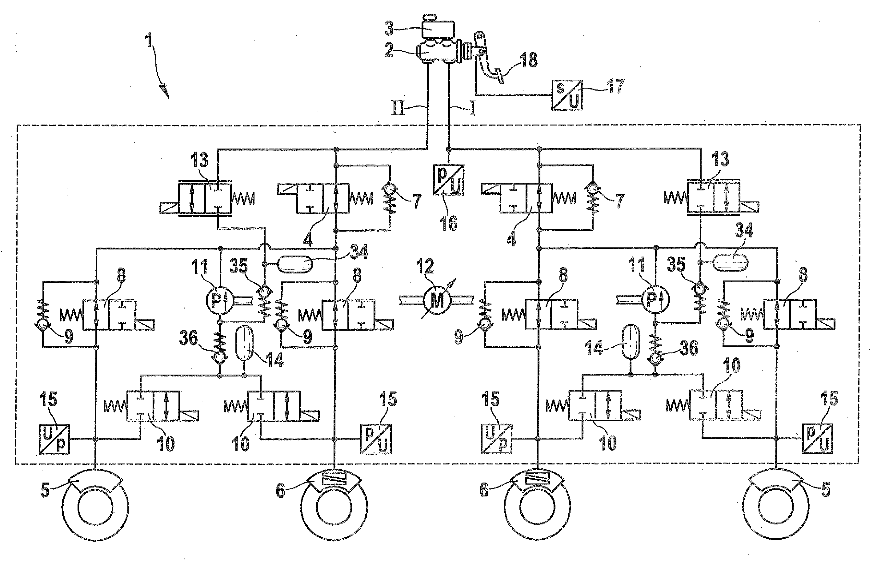
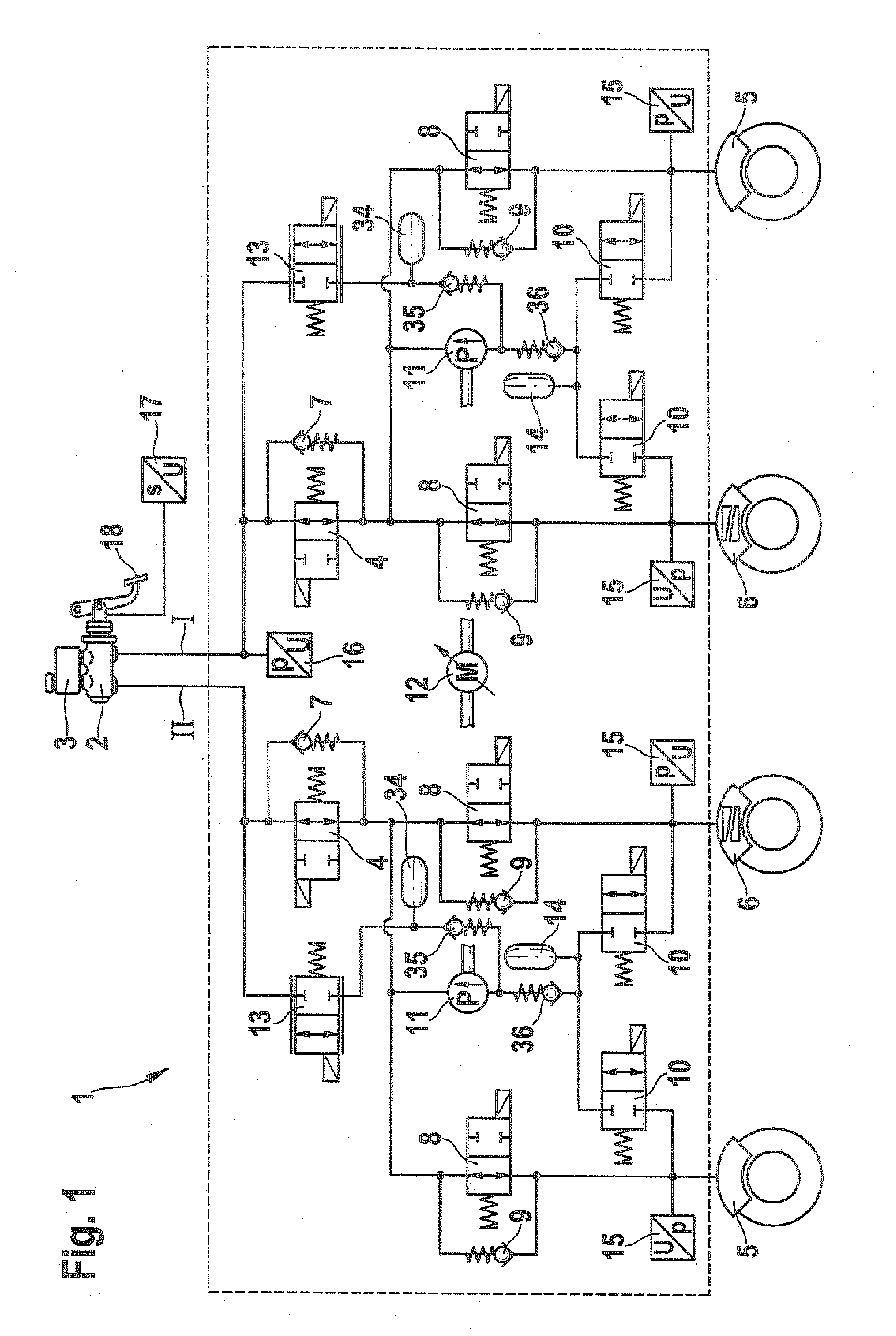
[0016]The hydraulic vehicle brake system 1 according to the invention shown in the drawings is equipped with wheel slip control (antilock brakes ABS; traction control system TCS; electronic stability program ESP). It is embodied in the form of a dual-circuit brake system with two brake circuits I, II that are connected to a brake master cylinder 2. The brake master cylinder 2 does not have a brake booster. The brake master cylinder 2 has a brake fluid reservoir 3 mounted on it. Each brake circuit I, II is connected to the brake master cylinder 2 via an isolating valve 4. The isolating valves 4 are 2 / 2-port directional control solenoid valves that are open in their currentless normal position. The isolating valves 4 are each hydraulically connected in parallel with a check valve 7 through which a flow can travel from the brake master cylinder 2 to the wheel brakes 5, 6. The isolating valves 4 of each brake circuit I, II are connected to the wheel brakes 5, 6 via brake pressure-increa...


PUM


Abstract

The invention relates to a hydraulic vehicle brake system with slip control. The invention proposes that wheel brakes at wheels of a front axle are of self-amplifying design in order to provide boosting of the brake force. An otherwise conventional vacuum brake force booster can be dispensed with. The invention further relates to a method for operating a hydraulic vehicle brake system, according to which, at high lining friction values, brake fluid is conducted, in a manner controlled by a valve, into a hydraulic reservoir.

Description

PRIOR ART[0001]The invention relates to a hydraulic vehicle brake system with the defining characteristics of the preamble to claim 1 and to a method for its operation, with the defining characteristics of the preamble to claim 11.[0002]Self-amplifying hydraulic wheel brakes for motor vehicles in the form of disc brakes are known. They have essentially the same design as conventional wheel brakes (disc brakes) without self-amplification and are supplemented with a self-amplification device. They therefore have a brake piston, which, when acted on by hydraulic pressure, presses a friction brake lining against a brake disc. For the self-amplification, at least one friction brake lining can be moved parallel to the brake disc in the circumferential or chord direction of the brake disc and rests against an auxiliary piston. When the disc brake is actuated, the rotating brake disc acts on the friction brake lining, which is pressed against it, in opposition to the auxiliary piston, thus ...

Claims


Application Information

Patent Timeline
Patent Type & Authority Applications(United States)
IPC IPC(8): B60T8/26B60T8/00
CPCB60T8/266B60T8/348B60T8/4291F16D2127/10B60T8/52F16D55/226B60T8/4872
Inventor BAUMANN, DIETMAR
Owner ROBERT BOSCH GMBH
Why Eureka
Try Eureka