Liquid deflecting baffle for an electric motor

a technology of electric motors and baffles, which is applied in the direction of magnetic circuit rotating parts, magnetic circuit shapes/forms/construction, windings, etc., can solve the problems of affecting the operation of the motor, the case cannot be completely sealed from outside contaminants, and the openings on the back intake side of the motor are particularly susceptible to water or other liquid entry, so as to achieve the effect of cooling the motor

Inactive Publication Date: 2010-05-06
NIDEC MOTOR CORP
View PDF7 Cites 36 Cited by
  • Summary
  • Abstract
  • Description
  • Claims
  • Application Information

AI Technical Summary

Benefits of technology

[0009]The present invention provides a fluid deflecting baffle for use on a horizontal axis electric motor to be used in an environment where liquid may otherwise pass through a vent opening in the lower margin of an endshield of the motor. The baffle is secureable to the endshield and extends in a partial covering relationship with the vent opening. A baffle secured to the external side of the endshield would preferably become part of a new cover for a typical electric motor, while a baffle secured to the internal side of the endshield would reduce the risk of liquid reaching a center zone of the interior of the motor chamber. In such a situation, liquid would tend to move to the radially outer region of the endshield due to the centripetal forces created by the fan, and travel with a low velocity in small gaps between the stator and the case and exit the chamber through exhaust openings in the case. The baffle includes a vent passage therethrough and has at least one liquid flow obstructing louver that extends across the vent opening to deflect liquid away from the vent passage while allowing venting air to flow through the vent passage and effectively cool the motor. The louver includes a generally flat liquid deflection surface that is disposed at an oblique angle relative to the axis of the motor and at least partially faces a venting direction of incoming air and liquid.
[0010]It has been discovered that the louver of this inventive baffle provides significant and effective deflection of fluids that could otherwise enter the motor case unencumbered, while surprisingly allowing sufficient airflow through, such that the temperature difference compared to a baseline cover without a baffle is minimal. The profile of this louvered baffle takes advantage of the ability of the venting air (which has a relatively low density compared to the liquid) to change direction more quickly than any accompanying liquid (which has a relatively high density compared to the venting air). Contact by a mixed fluid with the louvered baffle, then, removes just enough energy from the liquid to leave only the gravitational acceleration component of its trajectory, thus diverting its otherwise axial path into the motor case. This louvered baffle, therefore, provides a unique combination of both effective deflection of axially flowing liquid while also permitting sufficient axial flowing venting air to effectively cool the motor.

Problems solved by technology

It is known that continued exposure to contaminants, particularly water or other liquids, can cause corrosion and wear to the internal motor components (e.g., the rotor or stator windings), sometimes leading to a premature failure of the motor.
Consequently, vent openings in the motor case are required, and the case cannot be entirely sealed from outside contaminants.
However, the combination of a stronger vacuum created by a larger pressure differential and the pulling of air from the back of the motor (often more exposed to outside elements) can leave openings on the back intake side of the motor particularly susceptible to water or other liquid entry.
Such prior art covers have been satisfactory in some respects, but these covers also suffer drawbacks as they allow liquids that may flow in a generally axial direction (from sources such as those identified above) to pass through the open area of the cover and directly into the motor case.
Once such liquid enters the motor case, the liquid can condense on the internal motor components, detrimentally shortening the effective life of the motor as described above.

Method used


Image

  • Liquid deflecting baffle for an electric motor
  • Liquid deflecting baffle for an electric motor
  • Liquid deflecting baffle for an electric motor

Examples


Embodiment Construction

[0031]The present invention is susceptible of embodiment in many different forms. While the drawings illustrate, and the specification describes, certain preferred embodiments of the invention, it is to be understood that such disclosure is by way of example only. There is no intent to limit the principles of the present invention to the particular disclosed embodiments.

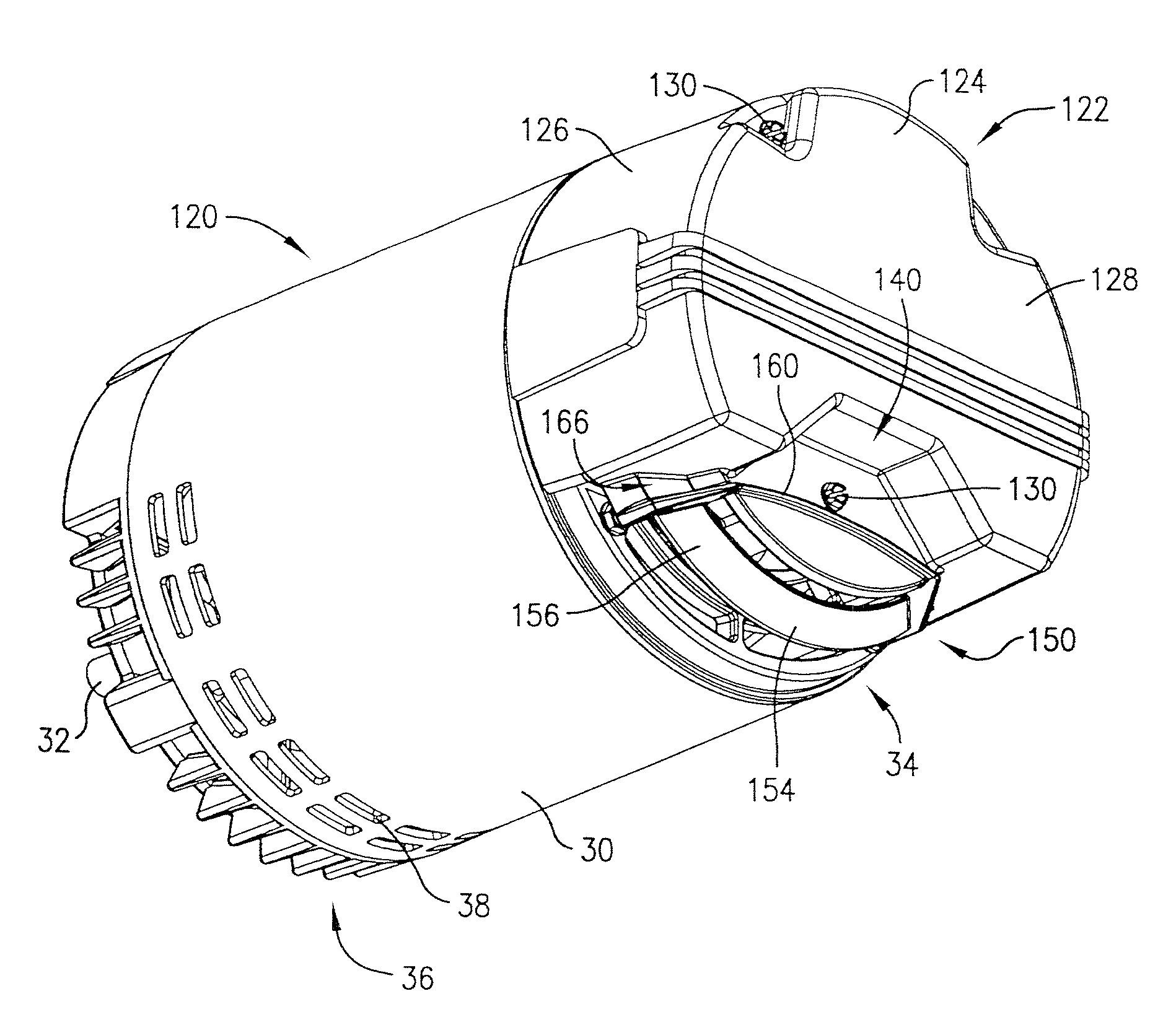
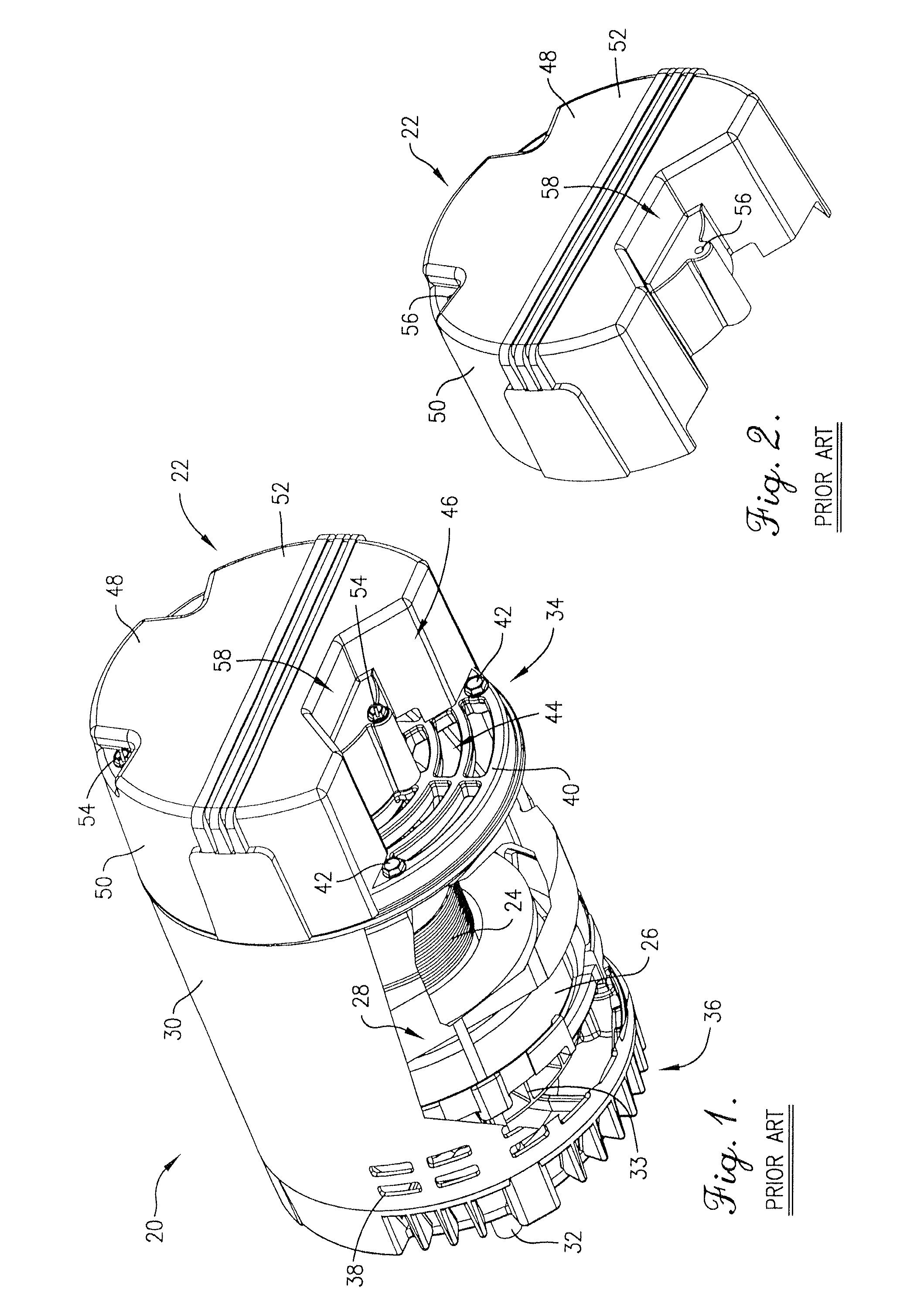
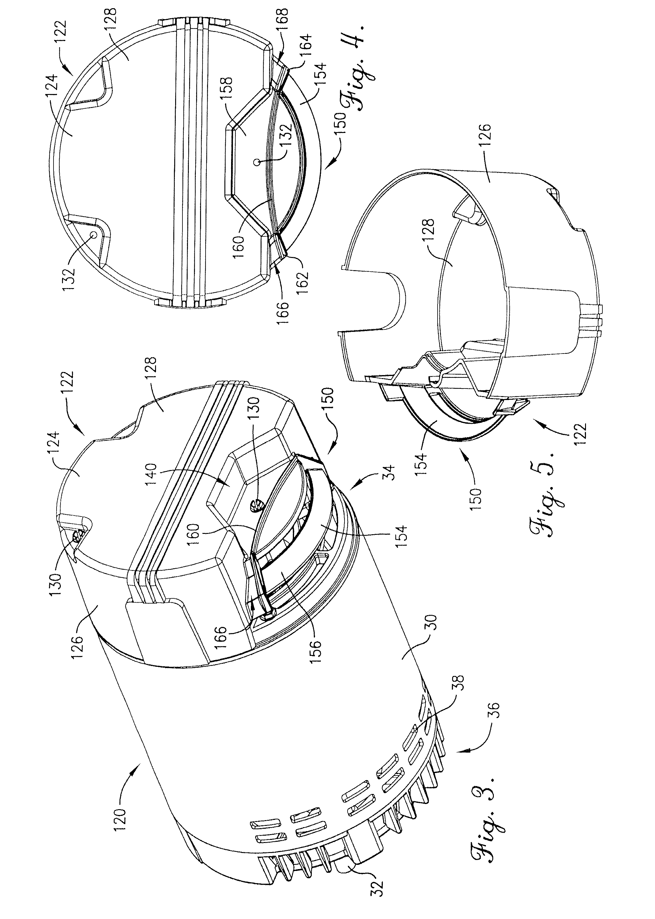
[0032]With initial reference to FIGS. 1 and 2, a prior art electric motor 20 is depicted that includes a conventional cover 22 that allows venting air to pass through, but provides no protection against axially flowing liquids. The motor 20 broadly includes a rotor 24 and a stator 26, with the rotor 24 and the stator 26 both contained within an internal motor chamber 28 defined by a motor case 30. A shaft 32 projects outwardly from the motor 20 in an axial direction and a fan 33 turns with the shaft 32 to pull cooling vent air through the chamber 28 of the motor 20.

[0033]The motor case 30 is generally cylindrical and...


PUM


Abstract

A fluid deflecting baffle is provided for use on an electric motor to be used in an environment where liquid may otherwise pass through a vent opening in an endshield of the motor. The baffle is secureable to the endshield and extends in a partial covering relationship with the vent opening. The baffle includes a vent passage therethrough and has at least one liquid flow obstructing louver that extends across the vent opening to deflect liquid away from the vent passage while allowing venting air to flow through the vent passage. The louver includes a generally flat liquid deflection surface that is disposed at an oblique angle relative to the axis of the motor and at least partially faces a venting direction of incoming air and fluid.

Description

BACKGROUND OF THE INVENTION[0001]1. Field of the Invention[0002]The present invention relates generally to electric motors having a horizontal axis, such as open drip-proof motors, used in outdoor environments, such as to power a swimming pool pump. More specifically, the present invention concerns a fluid deflecting baffle secureable to an endshield of such a motor that includes a liquid flow obstructing louver with a generally flat liquid deflection surface disposed at an oblique angle relative to the axis of the motor.[0003]2. Discussion of the Prior Art[0004]Those of ordinary skill in the art will appreciate that electric motors need to be protected from outside contaminants in order to function properly. In particular, electric motors that are used in outdoor environments, such as open drip proof motors, need to protect the internal motor components from contaminants (e.g., rain, other liquids, or debris), which could otherwise damage the motor. It is known that continued expos...

Claims


Application Information

Patent Timeline
Patent Type & Authority Applications(United States)
IPC IPC(8): H02K9/00
CPCH02K5/10H02K5/20H02K9/06H02K5/207
Inventor VADILLO, JOSE L.HEILMAN, RAYMOND D.SCHRADER, JOHN G.ELLIS, II, JAMES D.JONES, PATRICK M.
Owner NIDEC MOTOR CORP
Why Eureka
Try Eureka