Motor structure with rotation detector

a technology of rotation detector and motor structure, which is applied in the direction of mechanical energy handling, dynamo-electric components, instruments, etc., can solve the problems of prone to deterioration of driving comfort, reduce noise influence, and prolong the length of the motor.

Inactive Publication Date: 2010-05-06
AISAN IND CO LTD
View PDF15 Cites 38 Cited by
  • Summary
  • Abstract
  • Description
  • Claims
  • Application Information

AI Technical Summary

Benefits of technology

[0011]The rotation detector is excited in a frequency region of 8 kHz to 10 kHz. Therefore, the rotation detector is likely to be influenced by disturbed electromagnetic noise from the motor (noise of a frequency of 7.2 kHz for a sixth-order motor (18000 rpm, four pairs of N-S poles)). Furthermore, the rotation detector has an iron core (a back core) and thus the magnetic field generated in the motor stator 202 gives a great noise to the resolver stator coil 204. This may lower the angle detection accuracy of the rotation detector.
[0012]In the inventions of JP 2007-124757A and JP 9-65617A, t...

Problems solved by technology

In vehicles, specifically, drivability...

Method used


Image

  • Motor structure with rotation detector
  • Motor structure with rotation detector
  • Motor structure with rotation detector

Examples


first embodiment

[0053]A detailed description of a first preferred embodiment of a motor structure with rotation detector embodying the present invention will now be given referring to the accompanying drawings.

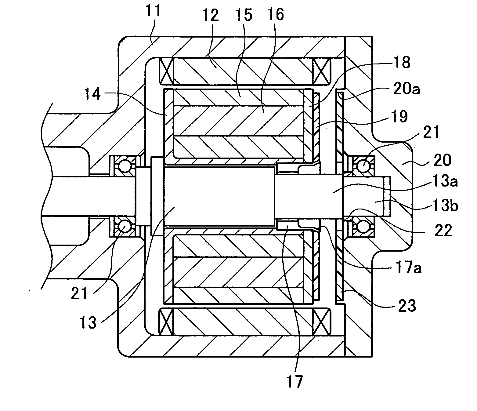
[0054]FIG. 1 is a cross sectional view of a motor structure internally having a resolver serving as a rotation detector in this embodiment. An outer casing includes a motor casing 11 and a lid casing 20. A motor stator 12 is fixed inside the motor casing 11. In the motor casing 11, furthermore, a bearing (first bearing) 21 is mounted. Similarly, another bearing (second bearing) 21 is mounted in the lid casing 20. A pair of the bearings 21 rotatably support a motor shaft 13 serving as a rotating shaft.

[0055]A motor rotor 15 is mounted on the motor shaft 13 through a guide 14. In the motor rotor 15, a permanent magnet 16 is fixedly contained. In FIG. 1, a left end face of the motor rotor 15 is in contact with the guide 14. In FIG. 1, a right end face of the motor rotor 15 is in contact with a s...

second embodiment

[0087]A second preferred embodiment of the structure of the motor with rotation detector according to the present invention will be described in detail with reference to the accompanying drawing.

[0088]The contents in the following embodiments mentioned below are substantially the same as those in the first embodiment and therefore the same parts or components are given the same reference signs as those in the first embodiment without repeating their explanations. The following description is focused on differences from the first embodiment.

[0089]FIG. 7 is a cross sectional view showing the structure of a motor internally having a resolver. As shown in FIG. 7, the shield plate 18 and the resolver rotor 19 are fixed to the stepped portion 13a of the motor shaft 13 through a spacer 61. To be specific, the spacer 61 is press-fitted between the stepped portion 13a and the inner diameter portions of the shield plate 18 and the resolver rotor 19, thereby positioning and fixing the shield p...

third embodiment

[0090]A third preferred embodiment of the structure of the motor with rotation detector according to the present invention will be explained in detail with the accompanying drawing.

[0091]FIG. 8 is a cross sectional view showing the structure of a motor internally having a resolver. As shown in FIG. 8, a shield plate 62 and the resolver rotor 19 are directly fixed to the stepped portion 13a of the motor shaft 13. To be specific, the stepped portion 13a is fitted in the inner diameter portions of the shield plate 62 and the rotor 19. The shield plate 62 and the rotor 19 are fixed to the motor shaft 13 with an adhesive.

[0092]The shield plate 62 includes, at its outermost peripheral edge, an annular protrusion 62a protruding toward the resolver rotor 19. This annular protrusion 62a can enhance shielding ability to the rotor 19.


PUM


Abstract

A casing of a motor with resolver includes a stator, a motor shaft rotatably supported by a bearing, a motor rotor integrally rotatable with the motor shaft, and a resolver for detecting a rotation angle of the motor rotor. The resolver includes a disc-shaped resolver stator held on the motor casing and having a surface on which a thin-film-shaped coil is formed, and a disc-shaped resolver rotor provided on an end face of the motor rotor and having a surface on which a thin-film-shaped coil is formed. Part of the motor casing holding the outer periphery of the resolver stator is formed as a shield portion cylindrically protruding along the outer periphery of the resolver rotor to the rotor. The motor casing and the shield portion are each made of a non-magnetic conductive material.

Description

CROSS-REFERENCE TO RELATED APPLICATIONS [0001]This application is based upon and claims the benefit of priority from each of the prior Japanese Patent Applications No. 2008-285848 filed on Nov. 6, 2008, No. 2009-100231 filed on Apr. 16, 2009, and No. 2009-109877 filed on Apr. 28, 2009, the entire contents of which are incorporated herein by reference.TECHNICAL FIELD [0002]The present invention relates to a motor structure with rotation detector, including a motor casing, a motor stator and a bearing provided in the motor casing, a rotating shaft rotatably supported in the motor casing by the bearing, a motor rotor rotatable with the rotating shaft, and a rotation detector for detecting a rotation angle of the motor rotor.BACKGROUND ART [0003]Heretofore, a hybrid electric vehicle and an electric vehicle use a high-power brushless motor. To control the brushless motor of the hybrid electric vehicle, it is necessary to accurately ascertain the rotation position (angle) of a motor rotat...

Claims


Application Information

Patent Timeline
IPC IPC(8): H02K11/00G01B7/30
CPCG01B7/30G01D5/208H02K29/12
Inventor MIYAZAKI, HIROAKINAKAMURA, TAKEHIDEINOUE, TOMOAKINAKAMURA, TAKAHIRO
Owner AISAN IND CO LTD
Why Eureka
Try Eureka