Inverter control device and ac motor control device using this inverter control device

a technology of inverter control device and control device, which is applied in the direction of motor/generator/converter stopper, dynamo-electric gear control, dynamo-electric converter control, etc., and can solve the problems of inability to use current control, reducing operating efficiency, and restricting the output capacity of the motor

Active Publication Date: 2010-05-06
KK TOSHIBA
View PDF0 Cites 18 Cited by
  • Summary
  • Abstract
  • Description
  • Claims
  • Application Information

AI Technical Summary

Benefits of technology

[0026]In view of the above, an object of the present invention is to provide an inverter control device and AC motor control device using this inverter capable of achieving current control in which PWM control changeover or changeover to phase control etc is unnecessary and with no steady error (or no steady-state error).

Problems solved by technology

Also, if the integrator output on the q axis side exceeds the level corresponding to the q axis voltage that is actually capable of being output, the system falls into a condition in which current control cannot be achieved and, so, in the high-speed region, it is necessary to weaken the flux rather earlier: thus the output capacity of the motor is restricted and operating efficiency is lowered.
Now, in control combining dq axis current control and PWM control, the current control lags, so it is not possible to use current control to suppress voltage fluctuations arising from the low order harmonic voltages that arise from PWM control, or arising from frequency differences of the carrier wave and the voltage reference.
However, in the event of changeover of the PWM control method, the output voltage changes and torque fluctuation is generated by the rapid change of current produced by this voltage change: in severe cases, the overcurrent protection system may be actuated.
Such adjustment to restrict the current references is troublesome and, depending on the application, it is sometimes not possible to adopt a changeover system involving restriction of the current references.
However, a characteristic drawback of current tracking PWM is the existence of a theoretically steady error (or steady-state error).
Since if this PWM signal is directly used for operational purposes, the frequency of the PWM signal is too high, an insensitive zone provided by hysteresis or a delay time imposed by a timer is provided: however, a steady error is produced by such an insensitive zone or delay time.
If the switching frequency is high, the steady error is small, but if the switching frequency is low the steady error increases and has a considerable effect on the performance of the motor.
Large drives for industrial use and main motor drives for electric vehicles etc employ large-current switching elements, so switching losses are considerable.
However, as described above, if the output (voltage instruction) of the current control circuit 16q exceeds the voltage output capability, control becomes impossible.
If this is done, there is a large leap in the fundamental / lower-order harmonics of the voltage, so it is not possible to simply perform changeover but, instead, a complex changeover control process must be performed.
Also, in the case of phase control, the current cannot be controlled at high speed, as in the case of current control.
In the high-speed region in which sine wave PWM is impossible, the current deviation becomes so large that it is difficult to say that current control is being performed: however, rather than control becoming impossible, the current changes in response to changes in the current reference.

Method used


Image

  • Inverter control device and ac motor control device using this inverter control device
  • Inverter control device and ac motor control device using this inverter control device
  • Inverter control device and ac motor control device using this inverter control device

Examples


Embodiment Construction

[0032]An embodiment of the present invention is described below with reference to the drawings.

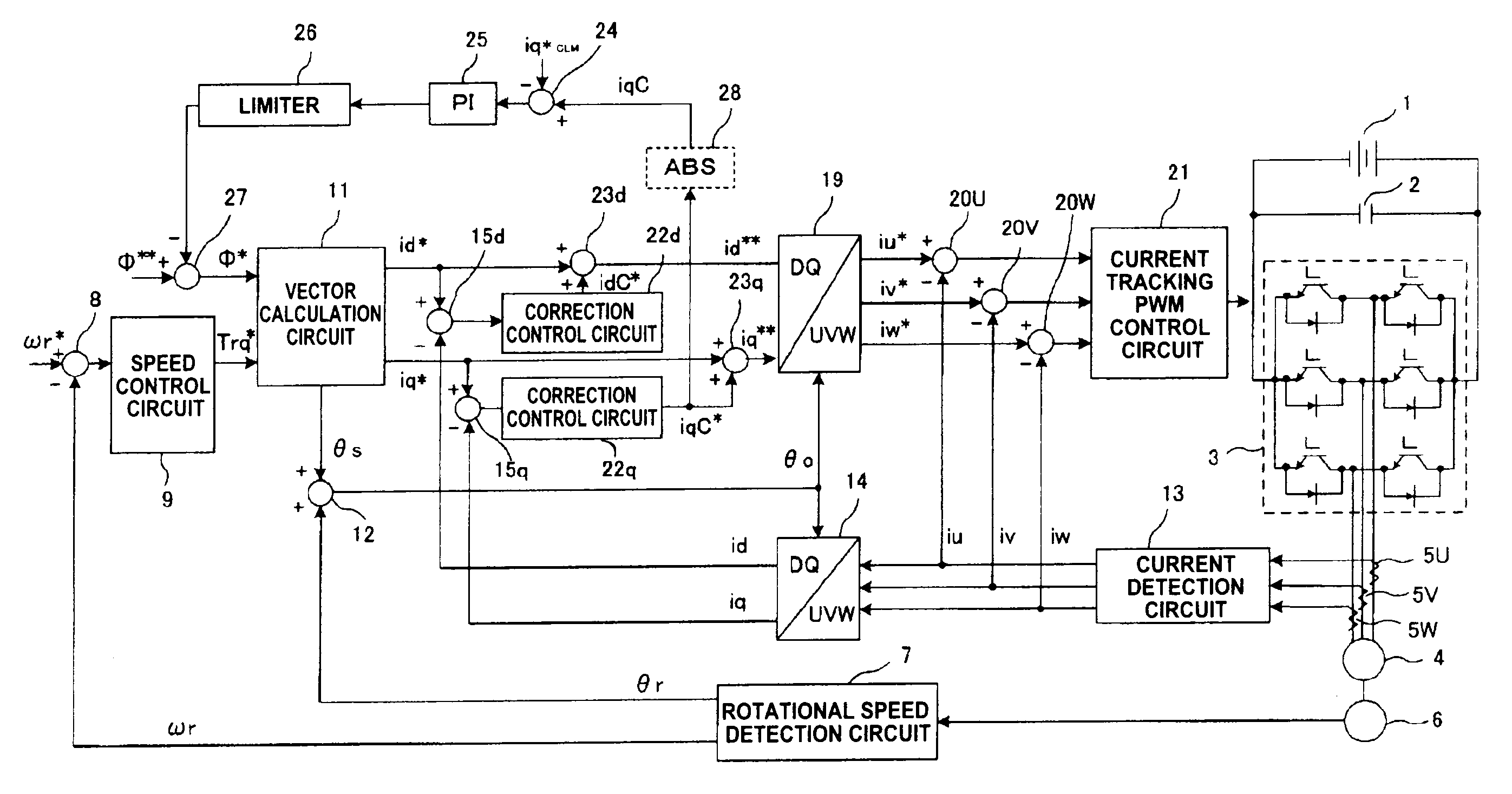
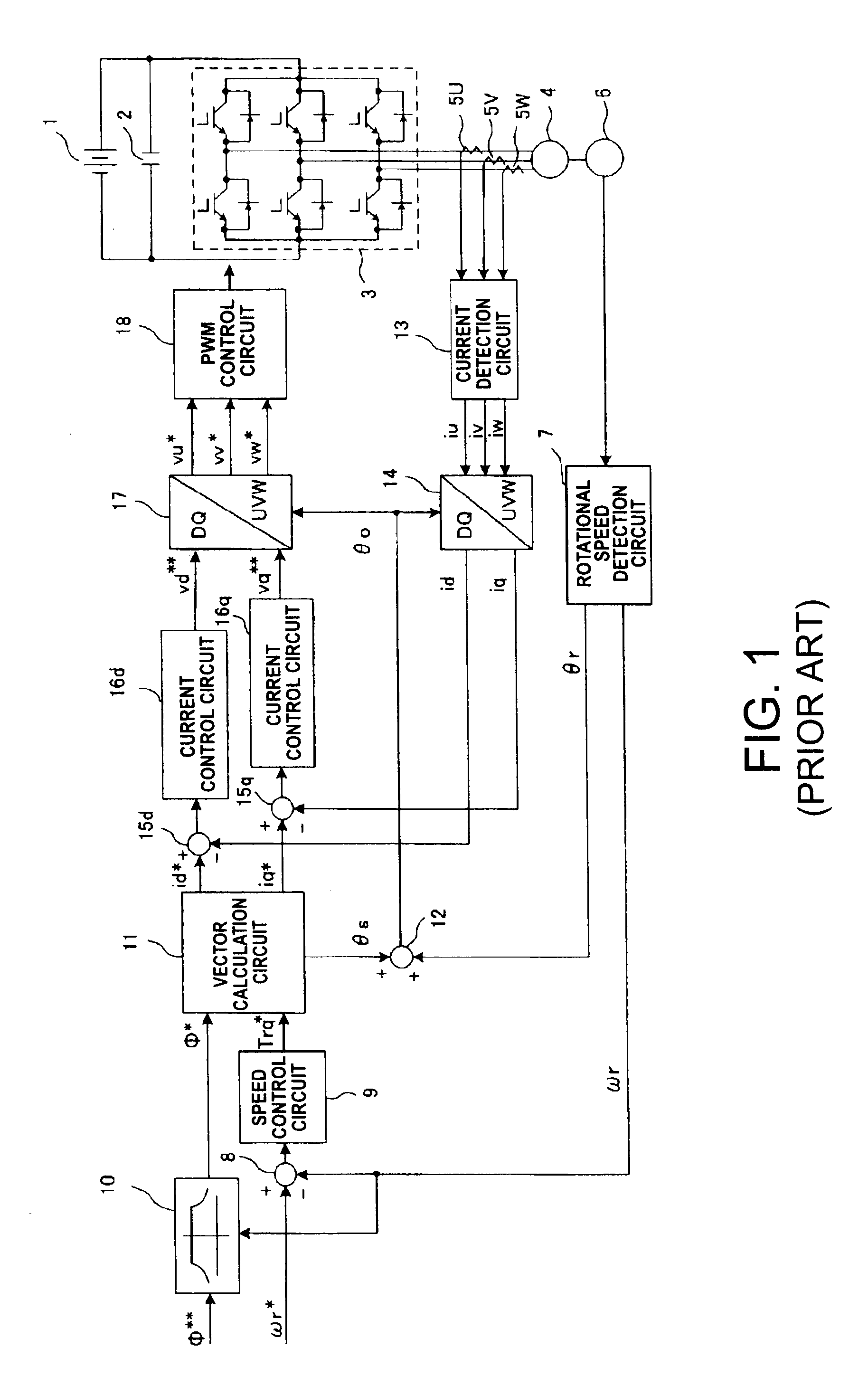
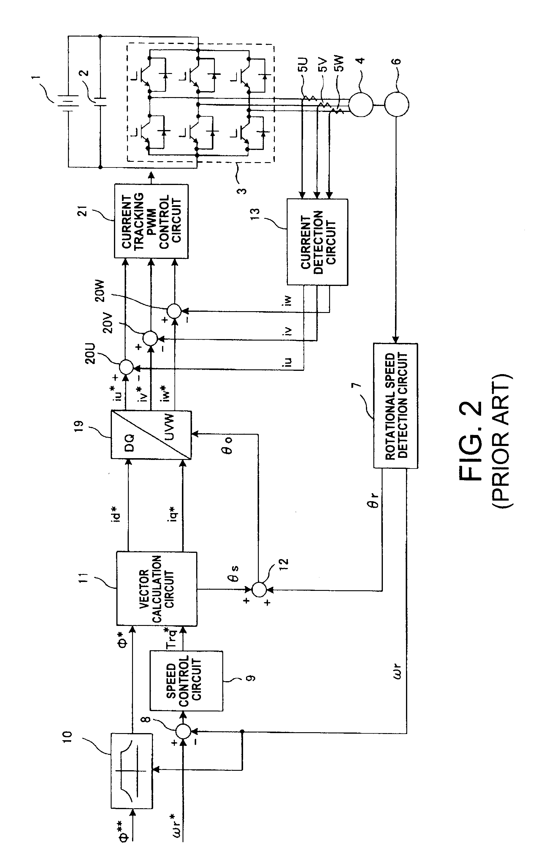
[0033]FIG. 3 is a layout diagram of an AC motor control device wherein an inverter control device according to an embodiment of the present invention is applied to control of a motor. In FIG. 3, elements that are the same as elements shown in FIG. 1 and FIG. 2 are given the same reference symbols and the description thereof is not repeated. Correction control circuits 22d, 22q, adders 23d, 23q, a subtractor 24, a flux weakening control circuit 25, a limiter 26, a subtractor 27 and absolute value circuit 28 are newly provided.

[0034]The correction control circuits 22d, 22q are provided in order to eliminate the steady deviation (or steady-state error): the correction control circuit 22d amplifies the current deviation (id*-id) of the current reference id* that is input to the subtractor 15d and the output current id that is output from the inverter 3, and outputs the result to the adder 23d....


PUM


Abstract

There is provided a current tracking PWM control circuit that directly generates PWM signals such that inverter output currents id, iq track PWM current references id**, iq**, using the results of comparison of the inverter output currents id, iq and PWM current references id**, iq**, in which, if current references id*, iq* exist, the result of adding the original current reference iq* and a correction signal iqC*, obtained by amplifying the deviation (iq*-iq) of the current reference iq* and iq, is used as the PWM current reference iq** on the q axis side for performing current control, but, in respect of the d axis side, the original current reference id* is used directly as the PWM current reference id** for performing current control.

Description

CROSS-REFERENCE TO RELATED APPLICATION[0001]This application claims benefit of priority from Japanese application No. JP 2007-29651 filed Feb. 8, 2007, the entire content of which is incorporated by reference herein.TECHNICAL FIELD[0002]The present invention relates to an inverter control device and an AC motor control device using this inverter control device that controls a voltage inverter (or a voltage-type inverter) that is widely used in fields such as power, industry and transportation.TECHNICAL BACKGROUND[0003]A typical method of controlling the current of a voltage inverter is proportional integral control of the dq axis current. FIG. 1 is a layout diagram showing a prior art example of an AC motor control device using such current control. In FIG. 1, a voltage inverter 3 inputs a voltage that is smoothed by a smoothing capacitor 2 that smoothes the DC voltage from a DC power source 1, converts the DC power from this DC power source 1 to 3-phase AC power and supplies this a...

Claims


Application Information

Patent Timeline
Patent Type & Authority Applications(United States)
IPC IPC(8): H02P21/00H02M7/48H02P21/22H02P23/07H02P23/08H02P23/16H02P27/04H02P27/06H02P27/08
CPCH02P21/0003
Inventor MAEKAWA, KATSUMIYASUI, KAZUYASUZUKI, KENTAROSHIOZAKI, YUICHI
Owner KK TOSHIBA
Why Eureka
Try Eureka