Current-mode phase rotator with partial phase switching

a current-mode phase rotator and phase switching technology, applied in pulse generators, pulse manipulation, pulse techniques, etc., can solve the problems of reduced power efficiency, more linear, impracticality of digital to analog converter implementation, etc., and achieve high power efficiency and reduce nonlinear behavior.

Inactive Publication Date: 2010-05-06
IBM CORP
View PDF10 Cites 29 Cited by
  • Summary
  • Abstract
  • Description
  • Claims
  • Application Information

AI Technical Summary

Benefits of technology

[0010]A better solution for a current-mode quadrature-input phase rotator is required to reduce the nonlinear behavior of a switched single digital to analog converter ...

Problems solved by technology

However, the complexity of such an ideal digital to analog converter makes implementation impractical and a piece-wise linear approximation of the intended sinusoidal shape of the output signal of such digital to analog converters is used instead.
The second type ...

Method used


Image

  • Current-mode phase rotator with partial phase switching
  • Current-mode phase rotator with partial phase switching
  • Current-mode phase rotator with partial phase switching

Examples


Embodiment Construction

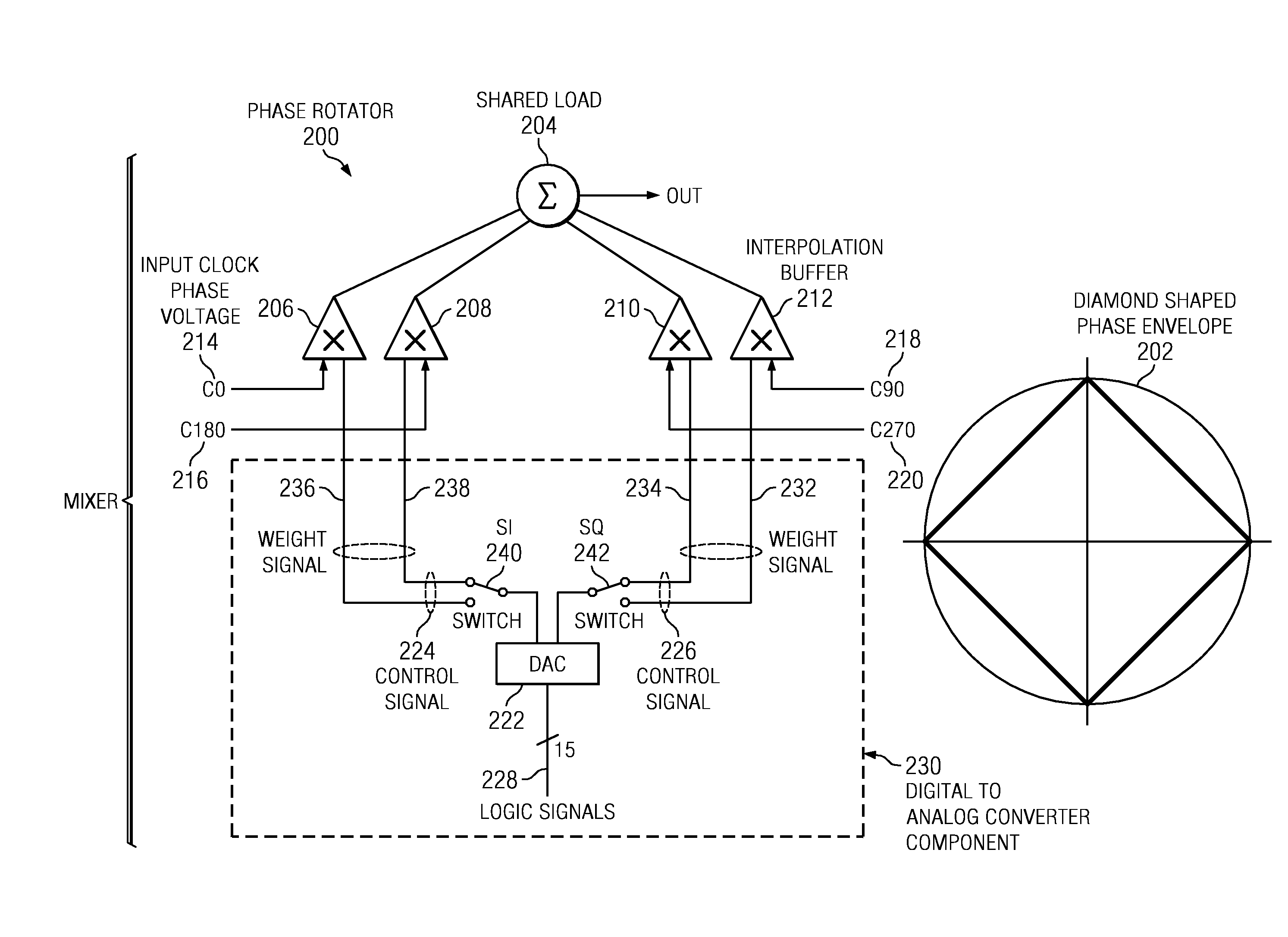
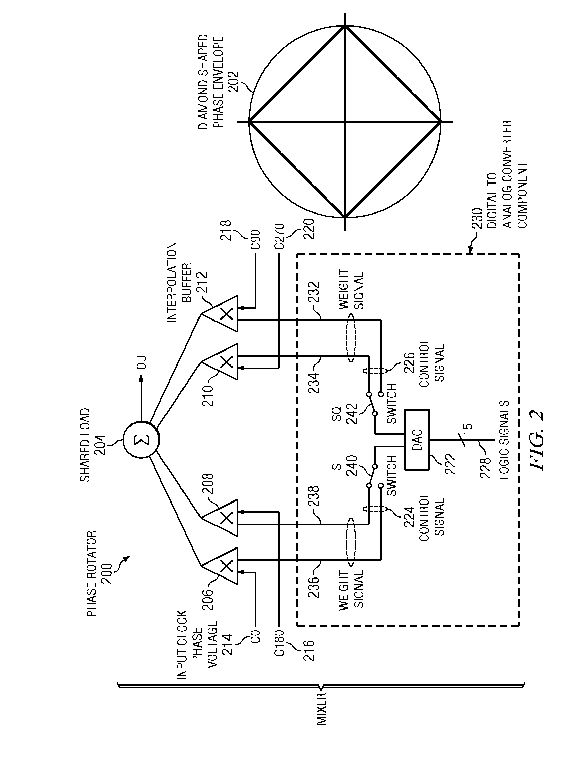
[0021]As will be appreciated by one skilled in the art, the present invention may be embodied as a system. Accordingly, the present invention may take the form of an entirely hardware embodiment, or an embodiment combining software and hardware aspects that may all generally be referred to herein as a “circuit,”“module” or “system.” The present invention is described below with reference to block diagrams of apparatus (systems) according to embodiments of the invention.

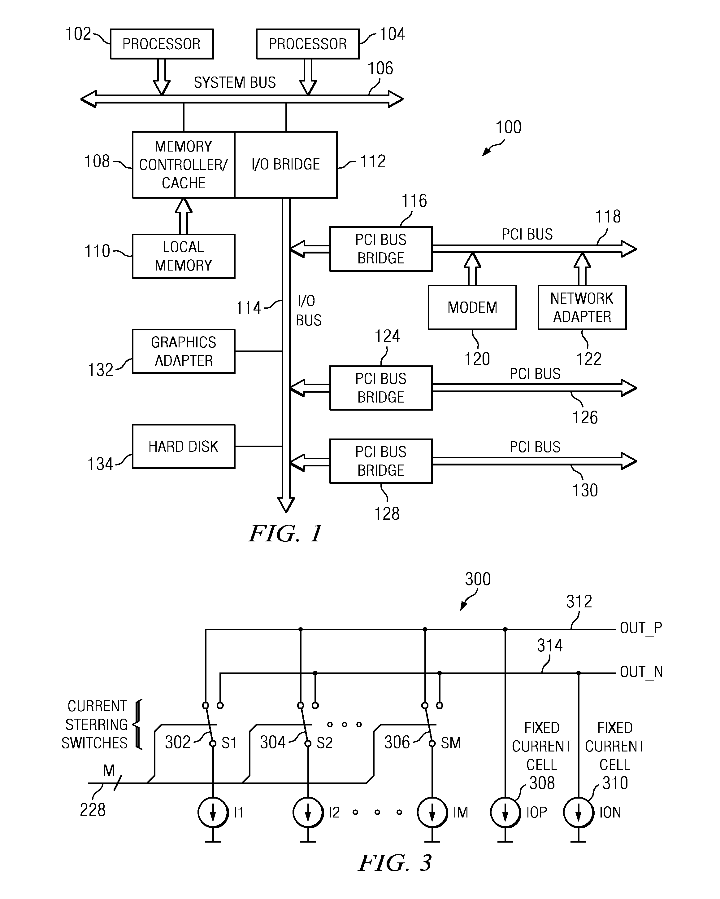
[0022]Referring to FIG. 1, a block diagram of a data processing system is depicted in accordance with a preferred embodiment of the present invention. Data processing system 100 may be a symmetric multiprocessor (SMP) system including plurality of processors 102 and 104 connected to system bus 106. Alternatively, a single processor system may be employed. Also connected to system bus 106 is memory controller / cache 108, which provides an interface to local memory 110. I / O bus bridge 112 is connected to system bus 106 a...


PUM


Abstract

In one illustrative embodiment, an apparatus for a current-mode phase rotator with partial input phase switching comprises a mixer, wherein the mixer is a four quadrant current-mode mixer comprised of four interpolation buffers, wherein each interpolation buffer receives as input a clock phase from a set of four equidistant clock phases, and a set of two-output current-steering digital to analog converters that supply tail currents to the mixer wherein a first digital to analog converter has additional switches to connect each of two outputs to one of two polarities of a given clock while each remaining digital to analog converter has no additional switches and has two outputs supplying current only to two different polarities of a same clock phase wherein steering the current during incremental rotation about a phase circle defines an octagonal shaped phase envelope.

Description

[0001]This application is a continuation-in-part of application Ser. No. 12 / 024,043, filed Jan. 31, 2008, status pending, which is incorporated by reference herein.[0002]This invention was made with United States Government support under Agreement No. HR0011-07-9-0002 awarded by DARPA. The Government has certain rights in the invention.BACKGROUND[0003]1. Field[0004]The disclosure relates generally to an improved data processing system for precision control of phases of clock signals, and more specifically, to a high-precision current-mode phase rotator.[0005]2. Description of the Related Art[0006]Phase rotators are critical components of clock subsystems of modern data processing and communications systems. Phase rotators modify, in a highly precise and reproducible fashion, the phase of clock signals within an unlimited phase range and therefore are capable of generating clock signals with programmable phase and frequency offsets. A common architecture used to design high-speed pha...

Claims


Application Information

Patent Timeline
IPC IPC(8): H03K5/13
CPCH03H11/20
Inventor RYLOV, SERGEY VLADIMIROVICH
Owner IBM CORP
Why Eureka
Try Eureka