
Measuring Video Quality Using Partial Decoding

Inactive Publication Date: 2010-05-06
CHEETAH TECH
View PDF10 Cites 46 Cited by
  • Summary
  • Abstract
  • Description
  • Claims
  • Application Information

AI Technical Summary

Benefits of technology

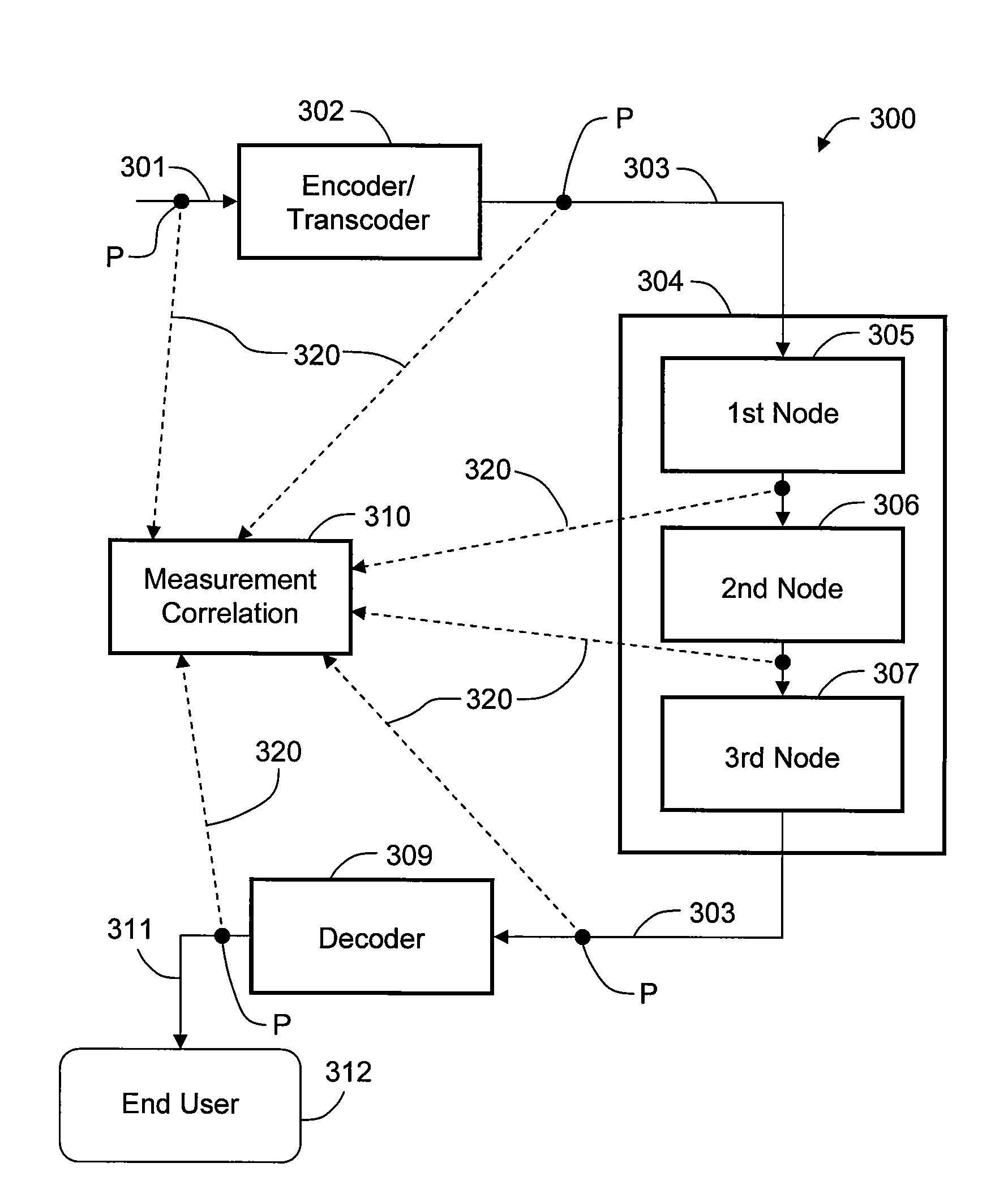
[0012]One or more embodiments of the invention provide a method and system for measuring the quality of video that is broadcast as a packet-based video stream. Video quality is measured using decoded pictures in combination with information extracted from the TS and video ES. The decoded pictures include selected frames and/or slices decoded from the video ES and are used to calculate video content metrics. Furthermore, an estimate of mean opinion score (MOS) for the video is generated from the video content metrics in combination with TS and/or ES metrics.
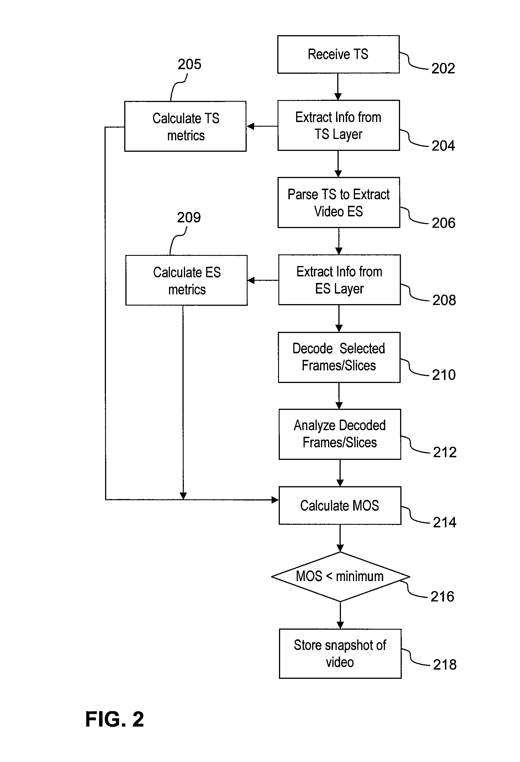
[0013]A method of measuring video quality according to a first embodiment includes the step of receiving a TS, parsing the TS to extract an ES containing video packets, extracting information from the TS and the ES, calculating video content metrics representative of the video quality from the ES, and generating a composite video quality score based on the video content metrics and one or both of the TS information and the ES information.
[0014]A method of measuring video quality according to a second embodiment includes the steps of receiving a video stre

Problems solved by technology

However, digital video, and particularly packet-based video, is subject to multiple sources of video distortions that can affect video quality as perceived by the end user.
Digital video processing artifacts can result in temporal video impairments, jerkiness, color distortions, blur, and loss of detail.
Due to the inherent loss of information, quantization is a significant source of visible artifacts.
Another source of compression-related video distortions is inaccurate prediction.
Many encoders employ predictive algorithms for more efficient encoding, but due to performance constraints, such algorithms can lead to visible artifacts, including blockiness, blur, color bleeding, and noise.
Network congestion, variation in network delay between the content provider and the end user, and other transmission problems can lead to a variety of video impairments when the packet stream is decoded at the end user.
For example, in motion-predictive coding, predicted frames and slices in the video rely on other parts of the video as a reference, so the loss of certain packets can lead to significant error propagation, and thus, the same packet loss rate can yield a substantially different picture quality at different times.
However, raw network metrics and other easily quantified metrics, e.g., packet loss rate or bit error rate, do not provide an accurate assessment of video quality as perceived by the end user.
In addition, video impairments are produced by a wide range of sources, some of which are not directly caused by the network, such as video pre- / post-processing and compression.
Due to the relatively small amount of data used as input for TS and ES metrics, they are computationally efficient and therefore highly scalable, but cannot accurately measure many video impairments.
This approach allows more accurate measurement of video impairments, but is computationally expensive.

Method used


Image

  • Measuring Video Quality Using Partial Decoding
  • Measuring Video Quality Using Partial Decoding
  • Measuring Video Quality Using Partial Decoding

Examples


Embodiment Construction

[0022]Embodiments of the invention contemplate a method of quantifying the quality of video contained in a packet-based video program using decoded pictures in combination with information extracted from the transport stream (TS) and / or elementary stream (ES) layers of the video bitstream. Information from the TS layer and the ES layer is derived from inspection of packets contained in the video stream. Each ES of interest is parsed from the TS, and each ES is itself parsed to extract information related to the video content, such as codec, bitrate, etc. The decoded pictures may include selected frames and / or slices decoded from the video ES, and are analyzed by one or more video content metrics known in the art. An estimate of mean opinion score (MOS) for the video is then generated from the video content metrics in combination with TS and / or ES quality metrics.

[0023]FIG. 2 is a block diagram illustrating a method 200 for analyzing quality of packet-based video, according to an emb...


PUM


Abstract

The quality of video that is broadcast as a packet-based video stream is measured using decoded pictures in combination with information extracted from the transport stream and elementary stream layers of the packet-based video stream. The decoded pictures include selected frames and / or slices decoded from the packet-based video stream and are used to generate video content metrics. A composite score for the video quality can be generated from the video content metrics in combination with quality metrics of the transport stream and / or the elementary stream. If the composite score falls below a minimum score, a snapshot of the video is captured for later analysis.

Description

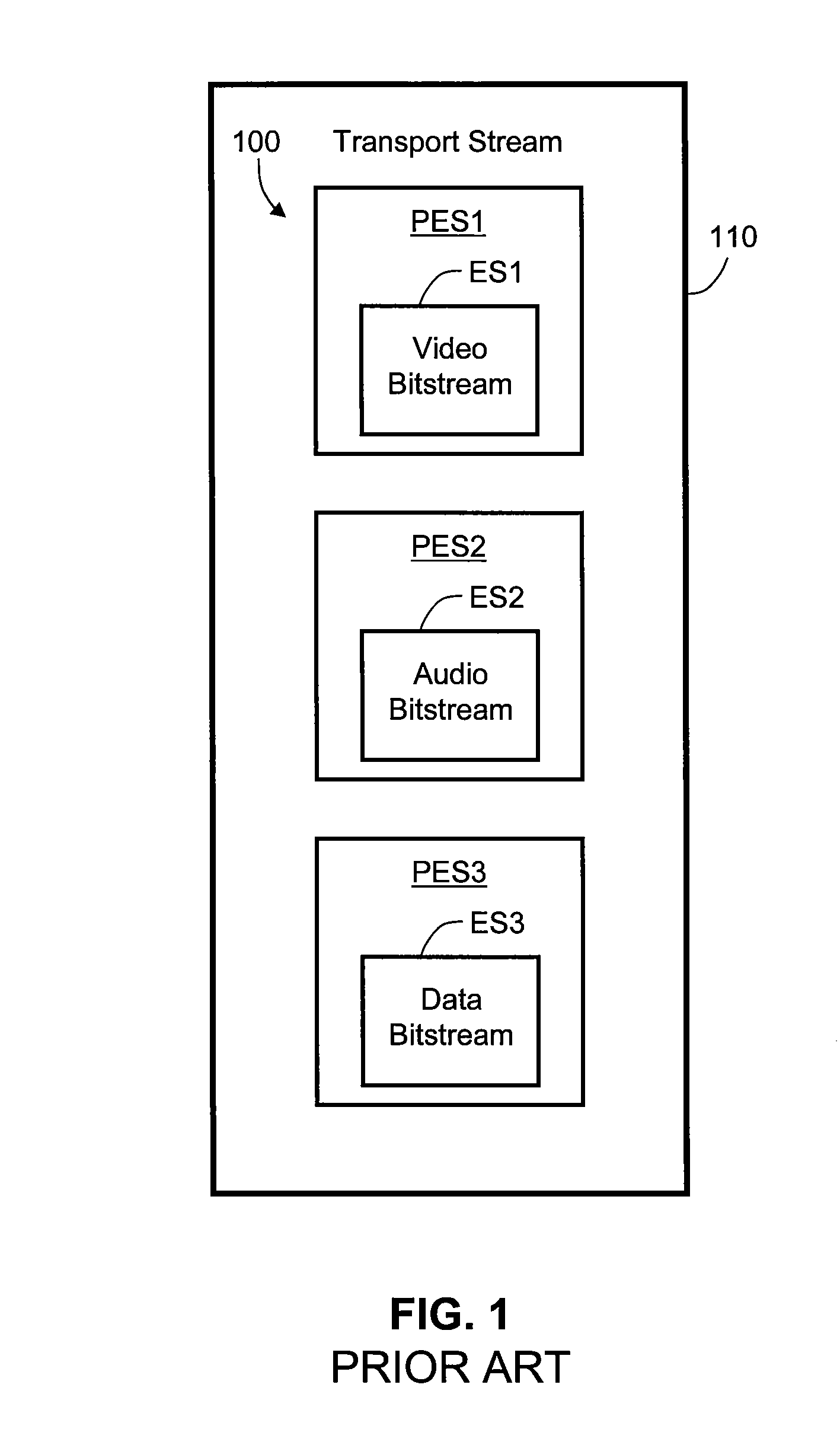
BACKGROUND OF THE INVENTION[0001]1. Field of the Invention[0002]Embodiments of the present invention relate generally to packet-based video systems and, more particularly, to a method and a system for measuring the video quality of a packet-based video stream.[0003]2. Description of the Related Art[0004]Packet-based video systems have seen continued increase in use through streaming, on demand, Internet protocol television (IPTV), and direct broadcast satellite (DBS) applications. Typically, in packet-based video systems, one or more video programs are encoded in parallel, and the encoded data are multiplexed onto a single channel. For example, in IPTV applications, a video encoder, a commonly used device or software application for digital video compression, reduces each video program to a bitstream, also referred to as an elementary stream (ES). The ES is then packetized for transmission to one or more end users. Typically, the packetized elementary stream, or PES, is encapsulated...

Claims


Application Information

Patent Timeline
IPC IPC(8): H04N17/00
CPCH04N7/52H04N17/004H04N21/235H04N21/4305H04N21/435H04N21/44209H04N21/4425H04N19/85
Inventor WINKLER, STEFANMOHANDAS, PRAVEENCOGNET, YVES
Owner CHEETAH TECH
Learn More