Reverse Flow Gas Gauge Proximity Sensor

a gas gauge and proximity sensor technology, applied in the field of proximity sensors, can solve the problems of serious shortcomings of sensors, significant challenges associated with creating proximity sensors of such accuracy, degrading or ruining the quality of the material surface or product being worked on, etc., and achieve the effect of eliminating errors

Active Publication Date: 2010-05-06
ASML HLDG NV
View PDF10 Cites 12 Cited by
  • Summary
  • Abstract
  • Description
  • Claims
  • Application Information

AI Technical Summary

Benefits of technology

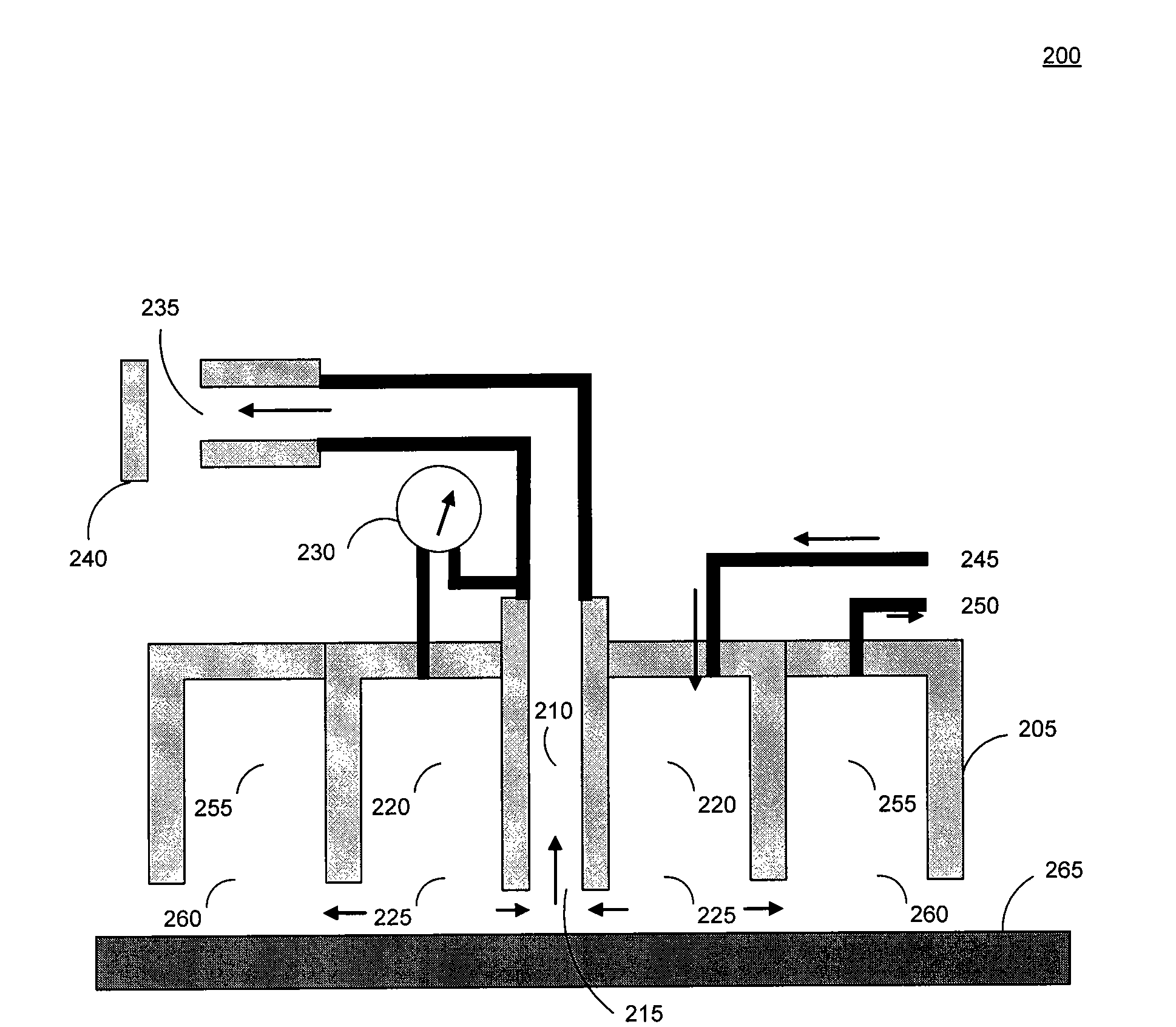
[0019]In a further embodiment of the present invention, a bridge version of the proximity sensor can be used. In this embodiment, two arms, a measurement arm formed by a measurement chamber, and a reference arm f...

Problems solved by technology

The challenges associated with creating a proximity sensor of such accuracy are significant, particularly in the context of lithography systems.
Occurrence of either situation may significantly degrade or ruin the quality of the material surface or product being worked upon.
However, these proximity sensors have serious shortcomings when used in lithographic projection systems because the physical properties of materials deposited on wafers may impact the accuracy of these sensors.
For example, capacitance gauges, being dependent on the concentration of electric charges, can yield spurious proximity readings in locations where one type of material (e.g., metal) is concentrated.
More ge...

Method used


Image

  • Reverse Flow Gas Gauge Proximity Sensor
  • Reverse Flow Gas Gauge Proximity Sensor
  • Reverse Flow Gas Gauge Proximity Sensor

Examples


Embodiment Construction

[0027]While the present invention is described herein with reference to illustrative embodiments for particular applications, it should be understood that the scope of the invention is not limited thereto. Those skilled in the art with access to the teachings provided herein will recognize additional modifications, applications, and embodiments within the scope thereof and additional fields in which the present invention would be of significant utility. The present invention is defined by the claims appended hereto.

[0028]The embodiment(s) described, and references in the specification to “one embodiment”, “an embodiment”, “an example embodiment”, etc., indicate that the embodiment(s) described may include a particular feature, structure, or characteristic, but every embodiment may not necessarily include the particular feature, structure, or characteristic. Moreover, such phrases are not necessarily referring to the same embodiment. Further, when a particular feature, structure, or ...


PUM


Abstract

A gas gauge proximity sensor supplying gas in a reverse flow direction from the injection chamber to the measurement chamber. Supplying gas in a reverse flow direction enables the transient behavior in the sensor to more rapidly stabilize, with a resulting increase in bandwidth. Optionally, a scavenger chamber can be used to remove the excess gas by locating a scavenger aperture of the scavenger chamber in close proximity to the exit aperture of the injection chamber. A bridge proximity sensor can be used with a reference chamber to receive gas flow from a location close to the exit aperture of the injection chamber in order to reduce common mode errors.

Description

CROSS REFERENCE TO RELATED APPLICATION(S)[0001]This applications claims the benefit under 35 U.S.C. 119(e) to U.S. Provisional Application No. 61 / 111,132, filed Nov. 4, 2008, which is incorporated by reference herein in its entirety.BACKGROUND[0002]1. Field of the Invention[0003]The present invention relates to a proximity sensor, and in particular to a proximity sensor for use in semiconductor lithographic applications.[0004]2. Related Art[0005]Many automated manufacturing processes require the sensing of the distance between a manufacturing tool and the product or material surface being worked upon. In some situations, such as semiconductor lithography, that distance must be measured with an accuracy approaching a nanometer.[0006]The challenges associated with creating a proximity sensor of such accuracy are significant, particularly in the context of lithography systems. In the lithography context, in addition to the needs to be non-intrusive and to accurately detect very small d...

Claims


Application Information

Patent Timeline
IPC IPC(8): G03B27/42G01L7/00
CPCG03B27/42G03F9/7057
Inventor LYONS, JOSEPH H.
Owner ASML HLDG NV
Why Eureka
Try Eureka