Electrostatic chuck assembly for plasma reactor

a plasma reactor and electrostatic chuck technology, which is applied in the direction of electrical equipment, basic electric elements, electric discharge tubes, etc., can solve the problems of shortening the cleaning period of the reaction chamber, increasing the number of particles, and shorten so as to reduce the equipment manufacturing cost of the plasma reactor, the effect of optimizing the structure and prolonging the lifetime of the electrostatic chuck cover

Inactive Publication Date: 2010-05-06
DMS CO LTD
View PDF3 Cites 4 Cited by
  • Summary
  • Abstract
  • Description
  • Claims
  • Application Information

AI Technical Summary

Benefits of technology

[0017]An aspect of exemplary embodiments of the present invention is to address at least the problems and / or disadvantages and to provide at least the advantages described below. Accordingly, an aspect of exemplary embodiments of the present invention is to provide an electrostatic chuck assembly for overcoming an incomplete coupling problem of a Radio Frequency (RF) couple ring and at the same time, by minimizing an incidence angle (θ) of plasma ions and optimizing a structure of the electrostatic chuck assembly such that the plasma ions are perpendicularly incident on a surface of an electrostatic chuck cover ring at an edge of an electrostatic chuck, making the RF couple ring unnecessary, lengthening the lifetime of the electrostatic chuck cover ring, and improving etching performance of a plasma reactor.
[0019]As described above, the electrostatic chuck assembly according to the present invention optimizes its structure, particularly, a structure of the electrostatic chuck, thereby being able to overcome an incomplete coupling problem of an RF couple ring and at the same time, by minimizing an incidence angle (θ) of plasma ions at an edge of the electrostatic chuck and making the plasma ions be perpendicularly incident on a surface of the electrostatic chuck cover ring at the edge of the electrostatic chuck, make installation of the RF couple ring unnecessary, lengthen the lifetime of the electrostatic chuck cover ring, and improve etching performance of a plasma reactor.
[0020]Also, by optimizing a length (G) of a protrusion part of the electrostatic chuck and a diameter (R1) of the protrusion part, there is no need to specifically design a shape of a focus ring outside the electrostatic chuck cover ring or add a complex additional element such as the RF couple ring to a lower part of the electrostatic chuck cover ring, thus being able to decrease an equipment manufacturing cost of a plasma reactor. On the other hand, by optimizing the length (G) of the protrusion part of the electrostatic chuck and the diameter (R1) of the protrusion part, protection of the electrostatic chuck and a process quality of an edge of a target object (i.e., a wafer) can be guaranteed.
[0021]Also, by optimizing the length (G) of the protrusion part of the electrostatic chuck and the diameter (R1) of the protrusion part, an etching profile of the electrostatic chuck cover ring has an ‘L’ shape (indicated by a B′ portion of FIG. 3) and thus, is able to obtain an effect of an equipment maintenance side such as lengthening the lifetime of the electrostatic chuck cover ring, decreasing an arcing phenomenon of the electrostatic chuck, decreasing the number of particles, lengthening a cleaning period of the reaction chamber, etc.

Problems solved by technology

Thus, there are secondary problems such as shortening the lifetime of the electrostatic chuck cover ring 40 resulting from the slant incidence of the plasma ions, increasing an arcing phenomenon of the electrostatic chuck, increasing the number of particles, shortening a cleaning period of the reaction chamber, etc.
Thus, because including the RF couple ring 30, the conventional electrostatic chuck assembly 10 has a problem that its structure is complex and also its manufacturing cost increases.
Thus, the electrostatic chuck assembly 10 still has an incomplete coupling problem of the RF couple ring 30.

Method used


Image

  • Electrostatic chuck assembly for plasma reactor
  • Electrostatic chuck assembly for plasma reactor
  • Electrostatic chuck assembly for plasma reactor

Examples


Embodiment Construction

[0032]Exemplary embodiments of the present invention will now be described in detail with reference to the annexed drawings. In the following description, a detailed description of known functions and configurations incorporated herein has been omitted for conciseness.

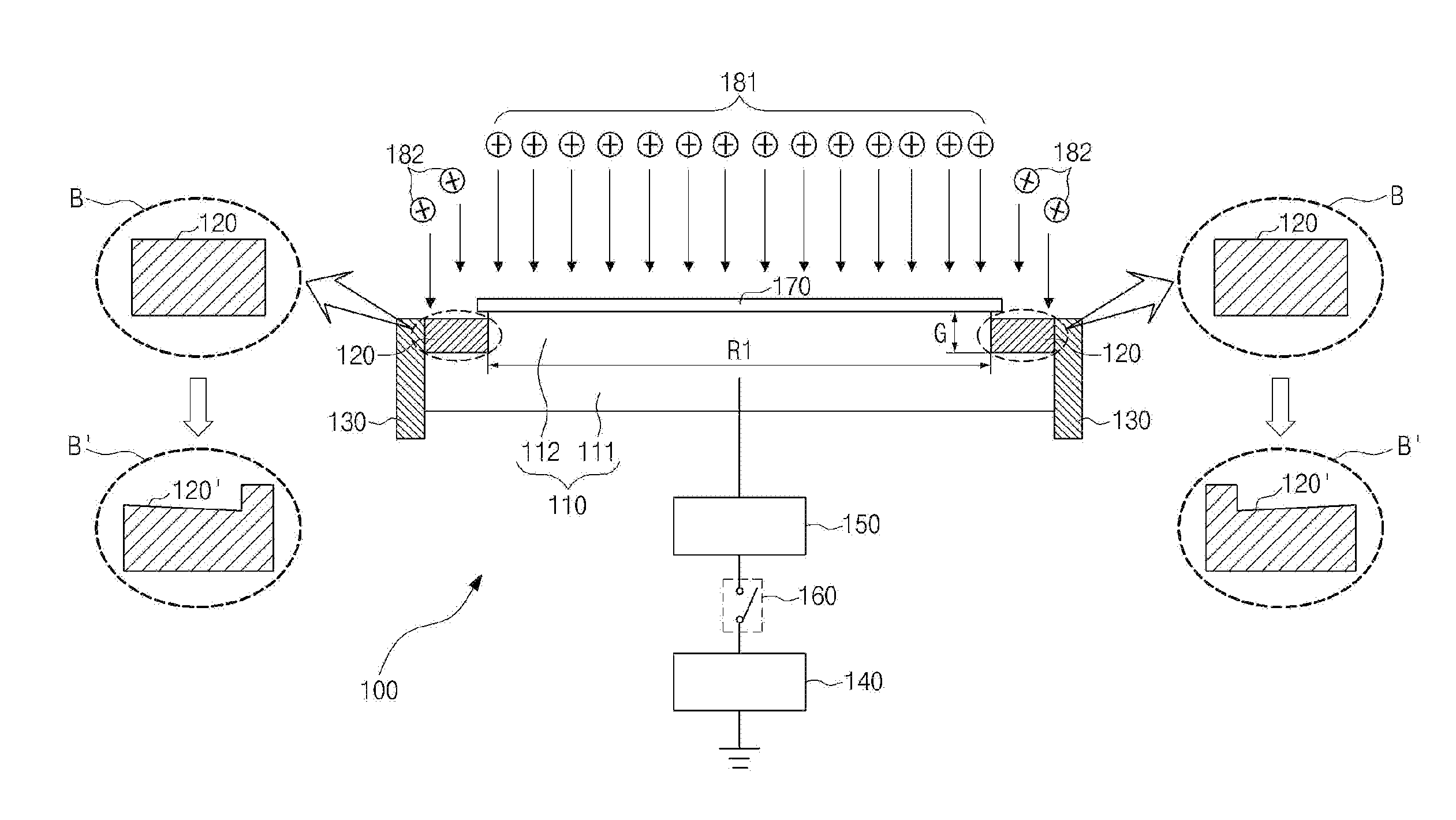
[0033]FIG. 3 is a schematic diagram illustrating an electrostatic chuck assembly according to an exemplary embodiment of the present invention. The electrostatic chuck assembly 100 includes an electrostatic chuck 110, an electrostatic chuck cover ring 120, and a cathode assembly cover ring 130. The electrostatic chuck 110 includes a body part 111 and a protrusion part 112. The body part 111 and the protrusion part 112 are each formed in a disk shape (FIG. 5). The protrusion part 112 is formed integrally with the body part 111 and protruded from the body part 111. A diameter (R1) of the protrusion part 112 is less than a diameter (R2 in FIG. 4) of the body part 111.

[0034]The electrostatic chuck cover ring 120 is dispose...


PUM


Abstract

Provided is an electrostatic chuck assembly for a plasma reactor. The assembly includes an electrostatic chuck, an electrostatic chuck cover ring, and a cathode assembly cover ring. The electrostatic chuck includes a body part and a protrusion part. The body part has a disk shape of a first diameter. The protrusion part is formed integrally with the body part and protrudes from the body part, and has a disk shape of a second diameter less than the first diameter. The electrostatic chuck cover ring is disposed to surround an outer circumference of the protrusion part. The cathode assembly cover ring is disposed at an upper part of the cathode assembly to surround an outer circumference of the electrostatic chuck cover ring and an outer circumference of the body part.

Description

CROSS REFERENCE[0001]This application claims foreign priority under Paris Convention and 35 U.S.C. §119 to each of Korean Patent Application No. 10-2008-0109242, filed 5 Nov. 2008 with the Korean Intellectual Property Office.BACKGROUND OF THE INVENTION[0002]1. Field of the Invention[0003]The present invention relates to a plasma reactor used in a semiconductor manufacturing process. More particularly, the present invention relates to an electrostatic chuck assembly of the plasma reactor.[0004]2. Description of the Related Art[0005]In general, an electrostatic chuck is positioned on a cathode assembly installed within a reaction chamber of a plasma reactor. Within the reaction chamber, the electrostatic chuck is used to fix a target object (e.g., a wafer or glass substrate) to be etched or deposited with etching material, to a cathode assembly. The target object is fixed to an upper part of the electrostatic chuck by an electrostatic attractive force that is generated when a Direct C...

Claims


Application Information

Patent Timeline
Patent Type & Authority Applications(United States)
IPC IPC(8): H01L21/683
CPCH01J37/32623H01J37/32642H01L21/6833H01L21/687
Inventor LEE, WEONMOOKCHAE, HWANKOOKPARK, KUNJOOKO, SUNGYONGKIM, MINSHIKKIM, KEEHYUN
Owner DMS CO LTD
Why Eureka
Try Eureka